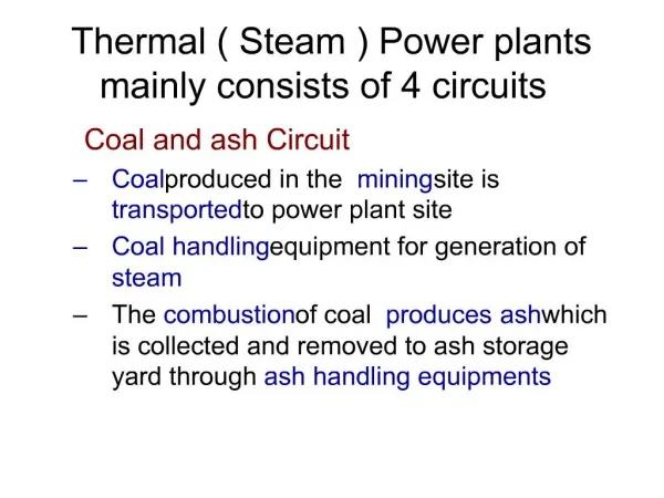
Download

1 / 48
480 likes | 536 Views
Explore the optimization of power plants by analyzing irreversible steam paths, minimizing energy losses, and maximizing turbine efficiency. Understand key factors and techniques for improving thermal power generation processes.

E N D
Irreversible Steam Path in Power Plants P M V Subbarao Professor Mechanical Engineering Department I I T Delhi Estimation and Control of Unwanted Entropy Generations …….
Steam Thermal Power Blade kinetic Power Steam kinetic Power Nozzle Losses Stage Losses Moving Blade Losses Sequence of Energy Losses in a Stage Isentropic efficiency of Nozzle Blade Friction Factor
Messrs. C. A. Parsons and Company, Ltd., Newcastle upon Tyne.
Experimental Data • The primary experimental data required were as follows :- (1) Initial steam pressure. (2) Initial steam temperature (3) Final steam pressure. (4) Torque (or weight in scale pan of dynamometer). (5) Revolutions per minute. (6) Steam consumption. (7) Mechanical and frictional losses. (8) Blade tip clearance leakage losses.
Optimal Selection of Number of Blades per Rotor Torque Force per Blade Total number of blades per rotor
“Biplane Effect” on Lift of Aerofoils Factor Force per Blade
Steam Thermal Power Blade kinetic Power Steam kinetic Power Nozzle Losses Stage Losses Moving Blade Losses Sequence of Energy Losses in a Stage
Measures for Irreversible Nozzles & Blades Isentropic efficiency of Nozzle Impulse Blade Friction Factor Reaction Blade Friction Factor
Irreversible Adiabatic Flow Through Turbine : SSSF in ht Exit,actual Exit,iso s Ideal work wiso = ht,in – ht,exit,iso Actual work wact = ht,in – ht,exit,act Internal Efficiency of a turbine s
Minimization of Losses : Focus for Innovation Optimized DoR designs Constant DoR design
Parson’s concept of multi-stage had produced an additional but marginal thermodynamic advantage.
Enthalpy Entropy Diagram for Multistage Turbine Turbine Inlet Stage 1 h Stage 2 Stage 3 Stage 4 Stage 5 Turbine Exit s
Internal Reheating due to Irreversibilities 3 4Ia 4Is 4IIa 4IIs 4IIIa 4IIIs 4IVa 4IVs T 4Va 4Vs 4VIa 4VIs 4s s
3 4Ia 4Is 4IIa 4IIs 4IIIa 4IIIs 4IVa 4IVs 4Va 4Vs 4VIa 4VIs 4s Steam Flow Path in a Multi Stage Turbine • Global available enthalpy for Power: • Internally available enthalpy for Power: 4IIss 4IIIss 4IVss 4Vss • Total actual stage work output per unit mass:
Measure for Irreversibilities Define Stage isentropic Efficiency: Global Isentropic efficiency of turbine:
Reheat Factor Due to Irreversibility qi is always positive. Therefore, • Multistage turbines will increase the possibility of recovering lost availability! • The larger the number of stages, the greater is the heat recovery. • The difference is called heat recovery factor, a. • General value of a is 0.04 to 0.06.
Compounding (Multi Staging) of an Impulse turbine • Compounding is done to reduce the rotational speed of the impulse turbine to practical limits. • Compounding is achieved by using more than one set of nozzles, blades, rotors, in a series, keyed to a common shaft; so that either the steam pressure or the jet velocity is absorbed by the turbine in stages. • Three main types of compounded impulse turbines are: • a) Pressure compounded Steam Turbine : The Rateau Design • b) velocity compounded Steam Turbine : The Curtis Design • c) pressure and velocity compounded Impulse turbines : The Rateau-curtis Design.
Impulse Turbines with pressure stages • Multistage turbines with pressure stages have found a wide field of usage in industry as prime movers (~ 10 MW). • The number pressure stages vary from 4 to 5. • The distribution of enthalpy drop in a large number of pressure stages enables the attainment of lower velocities for the steam flowing through the system of moving blades. • As a result more advantageous values of blade speed ratio and blade friction factor are obtained .
U U U b1,2 b1,1 b1,3 a2,3 a2,1 a2,2 a1,3 a1,1 a1,2 b2,2 b2,1 b2,3 Va2,3 Va1,2 Vr2,3 Va1,3 Vr1,1 Va1,1 Va2,1 Va2,2 Vr1,3 Vr1,2 Vr2,2 Vr2,1 A System of Velocity Triangles for Curtis Turbine
Current Practice • Purely multistage impulse turbines are mainly preferred in medium capacities of power generations.(30 – 60 MW units). • The main advantages are simplicity of construction, low costs, reliability and convenience of operation. • The height of blades in last stages of multistage turbine rapidly increase. • It is difficult to obtain tall, smooth and streamlined shape for the turbine. • Turbines of compound impulse stages are considered obsolete at present. • It is current practice for multistage turbines to allow for some amount enthalpy drop to take place in the moving blades as well.