Download
1 / 21
210 likes | 562 Views
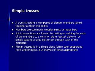
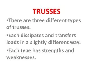
Chapter four Trusses. 4-1 INTRODUCTION A two dimensional truss A truss consists only of two-force members. in a truss it is required that all loads are applied only at the joints. 4-2 PLANE TRUSSES. Local and global coordinate systems:

E N D
Chapter fourTrusses Introduction to Finite Elements in Engineering
4-1 INTRODUCTION A two dimensional truss A truss consists only of two-force members. in a truss it is required that all loads are applied only at the joints. Introduction to Finite Elements in Engineering
4-2 PLANE TRUSSES Local and global coordinate systems: a)a Local coordinate system b)a global coordinate system Introduction to Finite Elements in Engineering
The Relationship between q’ and q is developed as follows: Transformation matrix: Formulas for calculating l and m: Introduction to Finite Elements in Engineering
Element Stiffness Matrix: a)In local coordinate system: The truss element is a one-dimensional element when viewed in the local coordinate system. b)In global coordinate system: consider the strain energy in local coordinates: Introduction to Finite Elements in Engineering
The strain energy in global coordinates: The element stiffness matrix in global coordinates: the element stiffness matrices are assembled to obtain the structural stiffness matrix. Introduction to Finite Elements in Engineering
Stress calculations: Introduction to Finite Elements in Engineering
Example 4.1 (a)Determine The element stiffness matrix for each element. (b) Assemble the structural stiffness matrix for the entire truss. (c)Using the elimination approach , solve for the nodal displacement. (d)Recover the stresses in each element. (e)Calculate the reaction forces. Introduction to Finite Elements in Engineering
Element stiffness matrices for element 1: Introduction to Finite Elements in Engineering
Element stiffness matrices for element 2,3 and 4: Introduction to Finite Elements in Engineering
b)Assembling the structural stiffness matrix K: For example: Introduction to Finite Elements in Engineering
(c)Using elimination approach: Boundary conditions are: The nodal displacement vector can therefore be written as: Introduction to Finite Elements in Engineering
(d)Stress calculations: The stress in members 1 and 2 is given by: Introduction to Finite Elements in Engineering
(e)Support reactions: We need to determine the reaction forces along dof’s 1,2,4,7 and 8,whitch correspond to fixed supports. R=KQ-F Introduction to Finite Elements in Engineering
Temperature effects: since a truss element is simply a one-dimensional element when viewed in the local coordinate system , the element Temperature load in the local coordinate system is given by: Where the initial strain associated with a temperature change is given by: since the potential energy associated with Temperature load vector is the same in magnitude whether measured in the local or global coordinate systems , we have: Introduction to Finite Elements in Engineering
Example 4.2 Determine the nodal displacement and element stresses as a result of temperature increase in bars 2 and 3. Introduction to Finite Elements in Engineering
Solution: The stiffness matrix for the truss has already been developed in example 4.1 , but the temperature load vector needs to be assembled. Introduction to Finite Elements in Engineering
The element stresses can now be obtained from eq. 4.24. for example: Introduction to Finite Elements in Engineering
Three-dimensional trusses: Local and global coordinate systems Introduction to Finite Elements in Engineering
Transformation matrix: Element stiffness matrix: Formulas for calculating l , m and n: Introduction to Finite Elements in Engineering
Temperature effects: Introduction to Finite Elements in Engineering