Download
1 / 33
350 likes | 749 Views
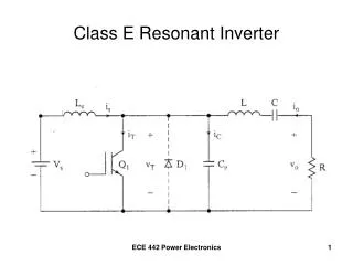
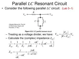
諧振電路 Resonant Circuit. 2012 年 4 月 23 日更新. Series RLC Circuit. 2. 2. Impedance. 某個 ω , Z 最小 。. 3. 3. Impedance vs. Frequency. 4. 4. Current. 5. 5. Current vs. Frequency. 6. 6. RLC 串聯諧振電路. 電阻、電容、電感三種元件以串聯型態出現在電路。 由於電容抗及電感抗在阻抗複數平面上相差 180° ,故電容抗與電感抗可能發生阻抗互消的結果。

E N D
諧振電路Resonant Circuit 2012年4月23日更新
Impedance 某個ω,Z最小。 3 3
Current 5 5
RLC串聯諧振電路 • 電阻、電容、電感三種元件以串聯型態出現在電路。 • 由於電容抗及電感抗在阻抗複數平面上相差180°,故電容抗與電感抗可能發生阻抗互消的結果。 • 當電路中電容抗與電感抗相等時,電路發生所謂的諧振,稱為RLC串聯諧振。 • 串聯RLC電路發生共振的條件?電容與電感的reactance相等!
Resonant Frequency The condition of resonance 9 9
At Resonance The impedance of the network 共振條件下,電路的阻抗(虛部為零),即net reactance為零,即power factor=1 The power delivered 10 10
Band Width 共振條件下,impedance最小 Selectivity curve:選擇可以通過的頻率範圍。 頻率越低,電容的電抗增加的幅度,高於電感的電抗,整體阻抗增加,電流降低。 頻率越高,電感的電抗增加的幅度,高於電容的電抗,整體阻抗增加,電流降低。 電流降低到0.707×peak value水準時的頻率f1與f2稱為half-power或cutoff或band frequencies。f1、f2與共振頻率f0等距離。兩者的間距稱為BW。電流降低到0.707×peak value水準時的功率;為共振頻率下的功率的一半。 11 11
Band Width 0.707的位置
Quality factor Q-selectivity The quality factor Q is defined by where Δω is the width of the resonant power curve at half maximum. Since that width turns out to be Δω = R/L, the value of Q can also be expressed as R越大,Q越小 13 13
Q vs. Selectivity A "quality factor" Q is a measure of that selectivity, and we speak of a circuit having a "high Q" if it is more narrowly selective. Q值越大,the sharpness of the resonance越大,band-pass filter變得更具選擇性,也就是說能通過band-pass filter的input signal的頻率將僅侷限於resonant frequency附近。 14 14
Selectivity vs. R The selectivity of a circuit is dependent upon the amount of resistance in the circuit. High Q R越大,Q越小 15 15
更新 Parallel RLC Circuit Focus on the condition
Impedance 更新 18 18
Voltage 19 19
Impedance 21
實習內容【一】 • 由已知電容與電感,推測諧振頻率。 • 調整輸入電壓頻率,並利用示波器量測跨越電阻的電壓,畫出電壓與輸入頻率的曲線,找出諧振頻率。 R=1 kΩ、C=0.1 μF、 L=0.01 mH, vs由信號產生器提供±15 V 計算理論諧振頻率
V1 (電壓源):yellow ; V3+V4(跨越L與C ):blueV2(跨越R):yellow ~ yellow-blue
V3 + V4 (跨越L+C):yellow V4(跨越C):blueV3 (跨越C):red=yellow-blue
實習內容【二】 • 由已知電容與電感,推測諧振頻率。 • 調整輸入電壓頻率,在電壓源後串接一1 kΩ的電阻R’,利用示波器量測跨越該電阻的電壓,畫出電壓與輸入頻率的曲線,找出諧振頻率。 R=1 kΩ、 C=0.1 μF、 L=0.01 mH, vs由信號產生器 提供±15 V 計算理論諧振頻率
v1 (電壓源):yellowVRLC (R、L、C並聯電路) :blueVR’ (跨越R’):red;i = vR’ /R’