Download
1 / 38
380 likes | 546 Views
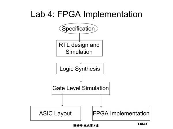
SOC FPGA Design Lab Discussion 5. SDR Lab Continued: DSP Blocks (Part I). Agenda. Discuss overall DSP architecture Channel selection filter Design CoreGen Implementation Discuss the tools which will be useful in development / verification of our design UDP streaming of data (as in Lab 4)

E N D
SOC FPGA Design LabDiscussion 5 SDR Lab Continued: DSP Blocks (Part I)
Agenda • Discuss overall DSP architecture • Channel selection filter • Design • CoreGen Implementation • Discuss the tools which will be useful in development / verification of our design • UDP streaming of data (as in Lab 4) • ISIM / Modelsim • Chipscope Introduction
Radio Receiver Core Audio 43.75 +/- 3 MHz 25 Msps 25 Million 14-bit numbers / sec 48k samples / second
Tuning / Downconversion Given that we have sampled at 25MHz, the input to the signal processing blocks is depicted below • Multiple information channels exist in this signal, a typical job of the DSP blockset would be to • “Tune” to the appropriate section of spectrum • Mix it to baseband • Filter out other channels • Reduce data rate (decimate) • Demodulate 2.75 9.25 0 (DC) 12.5MHz
Frequency Translation Graphics reprinted from : http://bruce.cs.tut.fi/invocom/p3-1/p3-1_2_1.htm We are going to accomplish this tunable translation with a DDS for generation of a complex sinusoid, followed by a complex mixer. Details next week.
Filtering • Two goals : • Remove contributions of signals from outside our channel • Reduce bandwidth so that data rate becomes manageable • 25 Msps is not necessary to represent our small channel bandwidth (ex : 150 kHz for FM radio)
Lab 5 : Filter Demonstration • Implement the channel selection filter which will be used in the SDR 48.828ksps 25Msps ADC L.P. Filter 512 FIFO uBlaze Ethernet to PC For analysis
Example • 25 Msps sample rate • 75kHz passband • By 100kHz we want >60dB attenuation • FIR Filter with <2048 taps will meet this requirement
FIR Implementation Delay • How many Multiply-Accumulate operations (MAC) are required per sample to implement the filter we designed? • What is the overall rate of MACs per second?
Scaling and Quantizing h[n] Numint = int32(Num*32700+0.5); fid=fopen('filt2030.coe','w'); fprintf(fid,'radix=10;\ncoefdata= \n'); fprintf(fid,'%d,\n',NumInt); fclose(fid); radix=10; coefdata= 15, -1, -1, -1, -1, …etc Scaling factor, How to choose? Result is : impulse response of filter in a “coe” file, which we will use later when designing the filter. Note that filter gain has changed though over the unity gain filter we designed in Matlab. Now, signals in the passband will come out x32700 over the input level.
Quantized Coefficients Overall, making the coefficients integers, (after multiplying by 32700) doesn’t affect our response too badly. With this scaling factor, our coefficient width is really only 9 bits. Some optimization between coefficient width and filter order could be undertaken if we chose.
freqz(numint,[1],100000); numint=round(Num*1024); numint=round(Num*1048500);
As an example for high performance FPGA capabilities – consider Virtex 6. DSP48E slices run up to 600MHz clock rates Theoretical :172 GMACs / sec – 1.2 TMACs/sec
Spartan 3A DSP • 84 * 250M = max 21 GMACs / sec • Our FPGA is capable of doing about ½ of what we want • There will be other features of the FPGA that need multipliers… • These figures should help put FPGA capabilities for DSP in perspective
Decimating FIR Filter Core component channel_filter port ( clk: IN std_logic; nd: IN std_logic; rfd: OUT std_logic; rdy: OUT std_logic; din: IN std_logic_VECTOR(15 downto 0); dout: OUT std_logic_VECTOR(31 downto 0)); end component; RDY : enable signal, result is present on rising edge of clock when this signal is high ND : enable signal, new data is latched on rising edge of clock when this is high RDY ND Din Dout CLK
Issues / Decisions • Clock domain for filter vs clock domain for A/D samples • 25, 50, higher? • Higher clocks allow fewer multipliers and higher performance, but may require clock domain crossing • Coefficient width / scaling • Less bits for coefficients will save RAM, but will decrease filter performance • Scaling factor and its effect on filter output will need to be understood and compensated for.. Full scale input (12 bits) should map to full scale output (16 bits) • FIFO size • Not super important to change yet; but with reduced data rate, you can now stream UDP data continuously and use a much smaller FIFO
Development • Matlab Simulation • Use this to solve all the real DSP issues • Mixer frequency for tuning • Filter number of taps / coefficients • Scaling issues • FAST, easy to change
Development • Modelsim / VHDL Simulation • Is useful to prove functionality of your design in known situations • Sometimes difficult to fully model real world • Simulations of individual pieces (particularly those which you did not write) can be very informative • Even more so than documentation • COREGEN cores easily simulated
SOC Debugging • Premise : • Full simulation often impractical • Visibility of internal signals is helpful to thoroughly debug / verify a design • Even external signals can be difficult to probe on high density boards • To observe functionality of your system as it interacts with an unpredictable real world is crucial
SDR Debugging • Build proven reliable datapipes first: • i.e. your UDP or serial port • Build in the ability to send pieces of data from various points in the system out to be observed. • Ethernet data pipe developed in lab 4 can be used to grab data from different points in your signal processing chain • Simply provide a means for different things to be written into the FSL input FIFO.
Internal FPGA Logic Resources are used to capture internal signals / events Data is read out via JTAG cable Essentially a logic analyzer inside the FPGA FPGA resource limited Chipscope Pro
Example of Logic Analyzer view while system is running. Real data from target
Notes • ICON core uses a “BSCAN” resource much like the Microblaze MDM Debugger • Spartan 3A DSP has only 1! • Effort beyond the scope of this demo is required to get both working concurrently • Online description will follow • System without Microblaze, or without debuggable Microblaze is the easiest to experiment with first