Download

1 / 53
530 likes | 659 Views
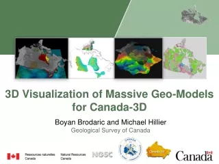
3D Engineered Models for Construction. Part I - Introduction September 2012. What is 3D Modeling?. Using a collection of intelligent computer objects that represent an original surface, in our case the design surface of a highway segment.

E N D
3D Engineered Models for Construction Part I - Introduction September 2012
What is 3D Modeling? • Using a collection of intelligent computer objects that represent an original surface, in our case the design surface of a highway segment. • The objects know their position in space and in some cases what they represent.
Why 3D Modeling? To better understand the design and locate possible conflicts and/or errors in the design.
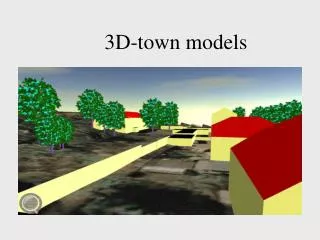
3D Transportation Model Courtesy of Iowa DOT
Another 3D Model Courtesy of Iowa DOT Courtesy of Iowa DOT
3D Cartesian Coordinates Graphic courtesy of Curtis Clabaugh, WYDOT
Mapping Capabilities Graphic courtesy of Curtis Clabaugh,WYDOT
A High Level Benefit of 3D Modeling • Improves communication between the owner, consultant, contractor, prefabricators, and materials suppliers Image courtesy of FHWA
What are Some General Benefits? • Easier to get stakeholder buy in • Identify possible errors before construction • Visualize subgrade and potential utility conflicts • Benefits to highway construction are similar to those realized in Building Information Modeling (BIM)
Top Benefits for Owners • Grade check 100% of constructed surface • Locate as-built utilities on the fly • Improved industry perception • Material cost savings Virtual construction to assess issues and improve communication prior to breaking ground! Photo courtesy of FHWA
Top Benefits for Contractors • Save labor of setting string line (paving) or stakes (grading) • Stringlesspaving may limit need for traffic closures • Increased productivity • Increased efficiency • Reduced labor costs Photo courtesy of FHWA
Top Benefits for A/E Firms • Identification of potential constructability issues earlier in the design process • Better value to clients • Improved accuracy in design • Visual model verification provides design QC Image courtesy of FHWA
Leaders in the Use of 3D Modeling • Wisconsin DOT • Iowa DOT • North Carolina DOT • Caltrans • Land developers • Design-builders
Other Functions 3D Models Support • Public outreach/marketing for projects • Utilities – coordination and early issue identification • 3D mapping and data storage • Clash detection • Earthwork quantities 3D Engineered Models are a Building Block of the Digital Jobsite
Challenges to Implementation • Time investment from 2D to 3D • Project selection – what characteristics to look for • Coordination across key stakeholders (contractor, owner, designers, suppliers, etc.)
What Challenges Need Consideration? • Where does “designing” stop and where does “detailing” begin? • What becomes the legal record of the design? • Can a 3D model be part of the contract documents? • Can electronic plans legally represent the design?
Plans and Evolution • 2D plans with profile andcross-section • 3D plans, electronic data files, and digital terrain models 3D modeling allows the existing and proposed features to be seen geospatially.
Limitations of 2D Plans in Construction Using a 3D model, we now have the capability to design and build accurately everywhere. • Human error in reading plans • Conflicts are not readily apparent • No surfaces, just cross-sections • We traditionally design and build accurately only at cross-sections
Key Stakeholders and Process Elements Several years old, sometimes
How is the Workflow Different from 2D to 3D? • Develop incremental detail of a virtual model by working continuously in a 3D environment • Extract the traditional 2D contract plans and bid item quantities from the 3D design model • Export 3D data files for construction and use of technology applications in the field
What Activities Can the Model Support? • A data package can be developed from the 3D model to support Automated Machine Guidance/Automated Machine Control“Plug and Play” equivalent once package is input to machine
What is Automated Machine Guidance (AMG)? • A process where design software and construction equipment are linked to direct the operation of machinery with a high level of precision, improving the speed and accuracy of the construction process.
Bulldozer Using AMG Photo courtesy of David White , Iowa State University
What the Machine Sees Courtesy of Iowa DOT
Types of Guidance Systems(Guidance Systems Evolution) Stakes String Lines String Lines with Sensors Lasers GPS Total Stations Photos courtesy of FHWA
Using Stakes – Traditional Method Provides visual guide/grade information Stakes set by surveyor Field personnel read stakes and guide machine operator Photo courtesy of FHWA
Using String Lines – Traditional Method Allows for machine control along a non-level surface Line represents a design surface at a particular elevation Photo courtesy of FHWA
Using Lasers/GPS Lasers are used for elevations A light bar on the cutting edge of a grader allows for up/down positioning GPS can be used to determine X-Y coordinates and pinpoint a location Users need different accuracies (we need “survey” level accuracy for highway projects compared with lower accuracy for recreational use or mapping)
Automated Machine Control Applications Scrapers, dozers, excavators, motor graders, milling machines, pavers Photos courtesy of David White, Iowa State University
Earthworks Photo courtesy of David White, Iowa State University
Typical Concrete Paving Using AMG Courtesy of Ed Jaselskis
Typical Asphalt Paving Using AMG Photo courtesy of David White, Iowa State University
Grading Photo courtesy of David White, Iowa State University
Colorado DOT I-70: The Problem • Expansive Soils Severe longitudinal undulations, rough ride, cracking • Widely varying asphalt depths – average 15” • Traditional mill/fill: consistent mill depth would maintain existing profile Photo courtesy of FHWA
CDOT I-70: The Process • No initial CDOT survey Contractor survey • Specs allowed for AMG for milling • Short timeline GPS survey – 5 passes at 25’ EB/WB • CDOT used MicroStationInRoads optimization to create 3D model with milling depths to balance humps and dips Photo courtesy of FHWA
CDOT I-70: The Project • Concrete “Whitetopping” pavement design required 8” minimum asphalt for 6” concrete • Full depth 9 ¼” concrete where < 8” asphalt remains after milling Photo courtesy of FHWA
CDOT I-70: AMG Milling • Robotic Total Station – 600’ intervals • Milling machine – automatically directed mill depth • Contractor’s surveyor performed independent check on original and milled surface Photo courtesy of FHWA
CDOT I-70: AMG Milling (cont’d) • Operation manually monitored • Screen reports deviation from pre-set milled elevation • Track height adjusted automatically to meet milled surface profile Photos courtesy of FHWA
CDOT I-70: AMG Milling (cont’d) • Greatly variable milling depths Image courtesy of FHWA Photo courtesy of FHWA
CDOT I-70: Lessons Learned • Colorado DOT • Better knowledge of technology prior to plan preparation • Need survey control by owner during construction • More accurate initial survey – tie in boundaries • Contractor • There should only be one 3D model • Boundaries were a problem – even in rural setting • 8% allowable concrete overrun is very tight • CDOT survey (pre-bid) more competitive bids
Benefits – Quality Assurance, Cost Savings, and Schedule Savings
Quality Assurance Without • 3D Modeling Photo courtesy of FHWA
Quality Assurance With 3D • Modeling Photo courtesy of David White, Iowa State University
Data Transfer: Benefits, Procedures, and Challenges Several years old, sometimes
Another Import/Export Scheme Leica Autodesk Trimble Topcon Bentley Carlson
Perceived AMG Benefits – Phase I Survey • Source: NCHRP 10-77
Productivity Impacts • Source: NCHRP 10-77