Download
1 / 9
90 likes | 240 Views
Solidworks Practice Homework Place in public directory by beginning of Class III. Solidworks Practice Housing. 25. • Open a new part file • Create Cylinder • Open a sketch on the Front (or plane 1) Plane • Draw a Construction line up from the origin

E N D
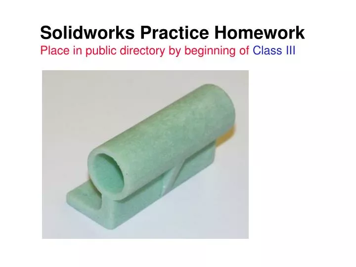
Solidworks Practice HomeworkPlace in public directory by beginning of Class III
Solidworks PracticeHousing 25 • • Open a new part file • • Create Cylinder • • Open a sketch on the Front (or plane 1) Plane • • Draw a Construction line up from the origin • • Draw a circle with the center on the construction line, and dimension it to be 25mm • • Add another Dimension from the origin to the circle center. Make it 30mm • • Select Extrude Feature, and select Mid Plane and enter 80mm • • Label this Cylinder 30
Solidworks PracticeHousing • Create Vertical Bar • • Open a sketch on the face of the cylinder • • Draw a vertical line up from the origin and through the center line of the Cylinder • • Click off the line, click on the top endpoint, and Add a relation to make it concentric with Cylinder • • Hit Extrude Boss/Base button • • On the Thin Feature Tab, Select Mid-Plane Type, and 7.5mm Wall Thickness • • Use the blind condition with 80mm setting. • • Click OK and label this Vertical Bar
Solidworks PracticeHousing • Create the Base • • On the face of the cylinder, open a sketchand draw a line from the origin to the left • • Dimension it 25mm. • • Hit the Extrude Base Button; Hit the Thin FeatureTab and select a • Wall Thickness of 7.5mm and Type: One-Direction. Make sure it is thickening upward.Again use Blind, 80mm. • • Label this Base 25
Solidworks PracticeHousing • Make inside hole • • Select the front face of the part and open a sketch • • Orient the view towards Front (from the standard views toolbar) • • Draw any Circle and Dimension it to 20mm diameter • • Hold down CTRL, Select the outer edge of the Cylinder feature, and right click to Add Relations, and choose Concentric • ª Select Extrude Cut Feature, and select Though All in the Type box • • Click OK and label this Hole 20
Solidworks PracticeHousing • Create a Rib • • Select the FrontPlane (or plane 1)and open a sketch • • On the Front view, draw a line from the bottom corner of the ‘L’ to a point on the outside Cylinder edge. Make sure that you are on the center plane. • • Highlight both the line and the Cylinder edge, and right click Add Relations, selecting Tangent • • Select Insert, Features, Rib • • The Property Manager appears. Select Mid plane Thickness of 7.5mm. For Extrusion Direction: Parallel to sketch. Toggle the Flip MaterialSide box. • • Select OK and label this Rib
Solidworks PracticeHousing • Create a Mounting Hole • • Highlight the top plane of the Base and • open a sketch • • Draw a circle, and Dimension it 5mm diameter • • Dimension it 7.5mm away from the Front face, and 7.5mm away from the side face furthest from the origin • • Select Extrude Cut; Type: Through All • • Click OK and label Mounting Hole 5 7.5 7.5
Solidworks PracticeHousing • Mirror Features • • Holding down CTRL key, highlight FrontPlane (or plane 1)and Mounting Hole in the Feature Manager tree. • • Select Insert, Pattern/Mirror, Mirror Feature; All your selections should be in the proper selection boxes. • • Confirm this, and click OK. Leave this named Mirror1
Solidworks PracticeHousing • Add a Fillet • • Select the edge on the inside elbow of the base • • Select Fillet • • Input a Radius of 7.5mm, press OK; leave this named Fillet1