Download
1 / 15
240 likes | 606 Views
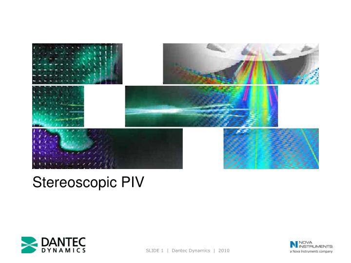
Stereoscopic PIV. Stereoscopic PIV. Theory of stereoscopic PIV Dantec Dynamics’ stereoscopic PIV software Application example: Stereoscopic PIV in an automotive wind tunnel (used as example throughout the slide show). Fundamentals of Stereo Vision. Displacement. True. seen from left.

E N D
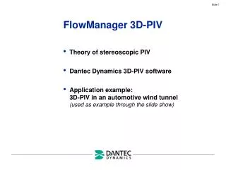
Stereoscopic PIV • Theory of stereoscopic PIV • Dantec Dynamics’ stereoscopic PIV software • Application example:Stereoscopic PIV in an automotive wind tunnel (used as example throughout the slide show)
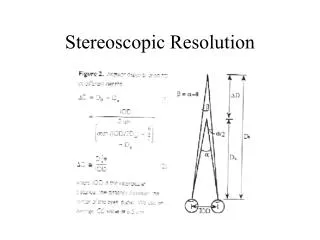
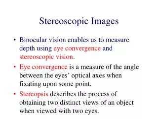
Fundamentals of Stereo Vision Displacement True seen from left displacement Displacement Focal plane = seen from right Centre of light sheet Left Right camera camera True 3D displacement ( X, Y, Z) is estimated from a pair of 2D displacements ( x, y) as seen from left and right camera respectively
Stereo Recording Geometry Focusing an off-axis camera requires tilting of the camera sensor (Scheimpflug condition) Stereoscopic evaluation requires a numerical model, describing how objects in space are mapped onto the sensor of each camera Parameters for the numerical model are determined through camera calibration
Camera Calibration Images of a calibration target are recorded. The target contains calibration markers in known positions. Comparing known marker positions with corresponding marker positions on each camera image, model parameters are adjusted to give the best possible fit.
Overlapping Fields of View Stereoscopic evaluation is possible only within the area covered by both cameras. Due to perspective distortion each camera covers a trapezoidal region of the light sheet. Careful alignment is required to maximize the overlap area. Interrogation grid is chosen to match the spatial resolution.
Left / Right 2D Vector Maps Left & Right camera images are recorded simultaneously. Conventional PIV processing produces 2D vector maps representing the flow field as seen from left and right. The vector maps are re-sampled in points corresponding to the interrogation grid. Combining left / right results, all three velocity components are calculated.
Overlap area withinterrogation grid Left 2D vector map Right 2D vector map Stereoscopic Reconstruction Resulting 3D vector map
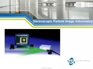
Dantec Dynamics Stereoscopic PIV System Components • Seeding • PIV-Laser(Double-cavity Nd:YAG) • Light guiding arm &Lightsheet optics • 2 cameras on Scheimpflug mounts • Calibration target • DynamicStudio PIV software • DynamicStudio stereoscopicPIV Add-on
Recipe for a Stereoscopic PIV Experiment • Carefully align the light sheet with the calibration target • Record calibration images in the desired measuring positionusing both cameras (Target defines the co-ordinate system!) • Perform camera calibration based on the calibration images • Record particle images with the laser turned on • Perform a Calibration Refinement to correct for the residual misalignment between calibration target and laser light sheet • Record particle images from your flow using both cameras • Calculate 2D-PIV vector maps • Calculate 3D vectors based on the two 2D PIV vector maps and the (refined) camera calibration