Download
1 / 64
710 likes | 1.39k Views
Computerized Train Control System. by: Shawn Lord Christian Thompson Advisor: Dr. Schertz. Presentation Outline. Project Overview Digital Train Control System Components Local Controller DCC Format DCC Encoder Switch Controller Sensor Controller Train Layout Design Implementation

E N D
Computerized Train Control System by: Shawn Lord Christian Thompson Advisor: Dr. Schertz
Presentation Outline • Project Overview • Digital Train Control • System Components • Local Controller • DCC Format • DCC Encoder • Switch Controller • Sensor Controller • Train Layout • Design Implementation • Results • Future Work
Project Overview • Digital Train Control System • Digital Control of Model Trains • Control of Track Equipment • Computer Interface • Goals • Fully control a digitally equipped locomotive • Control of switches and layout features • Sense train locations and layout state • Link all control to a central computer • Provide a train layout for future use • Provide supporting documentation
Digital Train Control • How Digital Control Works • Command Station • Takes User Input • Sends a command signal on rails of layout • Decoder Card • Resides in each locomotive • Derives power and data from signal on rails • Powers locomotives lights and motor
Digital Train Control • Standards • National Model Railroad Association (NMRA) • Sets Industry standards for model railroading • Recently incorporated standards for digital control • Digital Command Control (DCC) • NMRA standard for digital train control • Provides standards for communication with compatible Decoder Cards • Advantages • Locomotives are individually addressable • One signal to all rails on layout • Existing industry standards
System Components Block Diagram and Data Flow Controller Application Local Controller DCC Encoder
Local Controller • Handles low level control of train layout • Receives commands over serial link with PC • Creates serial packet for control of locomotives • Controls switches and accessories • Polls track sensors for position reporting • Implementation • 8051 microprocessor • Programmable Logic Device (FPGA) • Signal buffering circuitry
Local Controller • Command List • Local Controller Commands • Reset All • Locomotive Commands • Send Override Packet • Send Service Mode Packet • Send From Command List • Add to Command List • Remove from Command List • Clear Command List
Local Controller • Command List (contd.) • Switch/Accessory Commands • Set one output • Clear one output • Pulse one output • Reset all outputs • Sensor Commands • Reset sensor timer • Return one sensor • Return all sensors
Program Flow Command from PC Command Processing Locomotive Add command to queue Continuously write commands out to Encoder Accessory or Switch Write command out to controller Sensor Poll sensor(s) Transmit sensor reading(s) to PC
Local Controller • Memory Allocation (Memory Mapped IO) • 0x00 – 0x07 • DCC Encoder • 0x08 – 0x7F • Output space • 0x80 – 0x8F • Sensor space
DCC Format • Transition based serial encoding • Bit times • 232us – ‘0’ bit • 116us – ‘1’ bit • Fully rectified signal provides power for trains
DCC Format • Basic Packet Format • Preamble – ten ones followed by a zero • Address – eight bits followed by a zero • Data – eight bits followed by a zero • Error Check – eight bits followed by a one {preamble}0{address}0{data}0{error check}1 • Speed Packet • 01DCSSSS • Other Packet Types
DCC Encoder • Receives data from Local Controller • Transmits data in DCC format • Connected to external bus of Local Controller • Interrupts Local Controller upon completion • Implemented in VHDL • Registers • 0x00 Command byte • 0x00 – 0x07 DCC Packet to transmit
DCC Encoder Software Flow transmit preamble check command byte command byte empty command byte present transmit idle packet transmit data bytes Interrupt processor on last bit
System Components Block Diagram and Data Flow Controller Application Local Controller DCC Encoder
Track Switches • Allow locomotives to change paths • Solenoid Controlled • Double throw solenoid • Requires 12v 5ms pulse • Motor Controlled • Small gear motor • Requires 12v signal • Motor stalls upon end of travel
Switch / Accessory Controller • Connected to external bus of Local Controller • Latches data from Local Controller • 16 outputs total • 8 switches • 16 accessories • Sinks 600mA continuous or 3A pulsed • Addresses • Address + 0 Latch A • Address + 1 Latch B
Sensors • Allow Location of locomotive on layout • Layout divided into 21 blocks • Current sensor on each block • Current sensing • 1ohm current sense resistor • Differential voltage amplifier
Sensor Controller • Connected to A/D input of Local Controller • Data Latched from External Bus • 000C 0DDD • C – enables controller • DDD – selects 1 of 8 analog inputs • 8 inputs • Selected by analog switch • Inputs filtered using an RC filter
Train Layout • Designed for future use • 2 separate loops • 2 loopbacks • 1 crossover • 5 single ended sidings • 4 track train yard • 1 pass through siding
XS-40 Implementation of Design • XS-40 FPGA Prototyping Board • Manufactured by XESS Corporation • Xilinx 4005E-pc84 FPGA chip • 8031 uC • 128byte SRAM • Used to implement Design • Local Controller uses 8031 • DCC Encoder implemented on FPGA • Interface Board Designed • A to D converter • 256byte EEprom Memory • External Bus
Results • Hardware • Train Layout Built and Wired • Two DCC Compatible Locomotives • Local Controller Designed and Implemented • Sensors Designed and Tested • Switches Designed and Tested • Controller Boards • (Main, Switch, Sensor) • Design and Layout complete • Not manufactured
Results • Software • Serial interface designed and Implemented • Train control designed and implemented • Switch control designed • No software support for sensors • No support for service mode packets
Future Work • Manufacture and Build Controller Boards • Software • Sensor polling • Service mode packets • Decoupling and Crash prevention
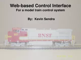
Web-based Control InterfaceFor a model train control system By: Kevin Sendra Advisors: Dr. Schertz Dr. Malinowski
Presentation Outline • Overview of the Project • Project Description • Results • Problems • Future work
Project Overview • Add-on to the Local Control System • Allows control and/or view of the layout from the internet
Project Description Block Diagram
Client Description • Allows the user to control the speed and direction of multiple trains • Displays connection information and command status (from server) • Image Map for switch control (no switch control currently)
Client Flowchart Start Get Parameters Thread Delay Thread Receive Create GUI Elements Send Command To Server Receive From Server Connect to Server Append to Text Area Wait .5s Start Threads Event Handling Close socket End threads
Local Computer • Server • Waits for a connection • Logs connections • Receives commands and sends them to the serial port • Acknowledges commands • Sets session length to 10 minutes • Webcam Software • Dorgem
Server Flowchart Server Start Thread Timeout Start Thread Compare Stored Time To Current Time Wait For A Connection Log Connection Store Time +10m Disconnect If Equal Wait For A Command Acknowledge Close Connection
Results • Working graphical user interface • Allows locomotive speed and direction controls • Displays command status • Working Server • Viewable webcam stream
Problems • The computer • Speed • Security and Software • Java versions and Internet Explorer or Netscape
Future Work to be Completed • Implement switch control • Allow a configuration file to set up certain elements of the interface
Train Control Train Control Train Control 800x600
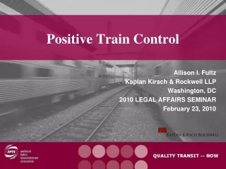
Local Computer Interface For A Digital Train Controller By: Zachary Kirkpatrick Advisor: Dr. Schertz
PresentationOverview • Introduction • Block Diagram • Functional Description • Design • Accomplishments • Complications • Conclusion
Introduction • Digital Train Controller • Local Computer Interface • User Input Instruction • Send Out Instruction • Train Moves
Block Diagram Altered Input Local User Input Computer Instruction Instruction
Functional Description • Input User Instructions • Decipher User Instructions • Alter Code Of Instructions • Send Out Instructions To Microprocessor
Design Flow Chart User Input Power Switch Speed Movement On Off Up Down Forward Reverse Track Train Go Back To User Input
Design • Write Software To Draw Control Buttons • Output The Appropriate Information For The Corresponding Button Pressed • Use MFC Library of C++