Download
1 / 48
490 likes | 749 Views
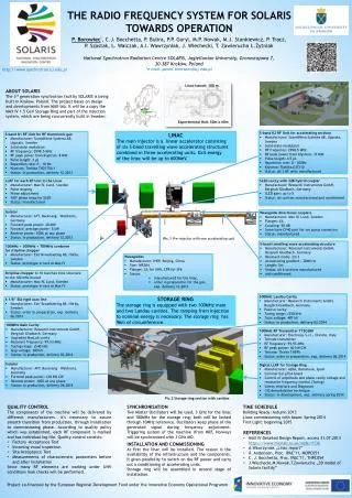
Built-In Self-Test for Radio Frequency System-On-Chip. Bruce Kim The University of Alabama. Outline. Proposed BIST Architecture Developed Equations Measurement Results Conclusions. Motivation. Today. Future. System-On-Board (SOB). System-On-Chip (SOC). RF Testing. Expensive

E N D
Built-In Self-Test for Radio Frequency System-On-Chip Bruce Kim The University of Alabama
Outline • Proposed BIST Architecture • Developed Equations • Measurement Results • Conclusions
Motivation Today Future System-On-Board (SOB) System-On-Chip (SOC)
RF Testing • Expensive • Labor intensive
What is BIST (Built-In Self-Test)? A test technique which allows the SOC to evaluate its own quality without expensive external equipment.
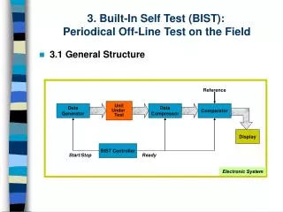
Test Flow Package Functional Test Singulated Wafer Level Testing Proposed BIST Functional Testing Proposed BIST (Go-No Go)
LO LO VGA ADC ADC DAC DAC Wireless Radio LNA Phase Shifter DSP Duplexer LO VGA Phase Shifter PA
Proposed RF BIST for LNA • S1 closed: Measure VT1 • S2 & S3 closed:Measure VT2
(1) (2) (3) Development of Equations
: Voltage gain of BIST : Voltage gain of Test Amplifier Fault-Free Input Impedance
Faulty-Case Input Impedance(VT2) : Voltage gain of BIST under faulty case
: Voltage gain of BIST Fault-Free Voltage Gain
: Voltage gain of BIST under faulty case Faulty-Case Voltage Gain (VT1, VT2)
Input Return Loss • Fault-Free Case : Input Return Loss of BIST • Faulty Case
Output Signal-to-Noise Ratio • Fault-Free Case kT: -204 dB B: signal bandwidth • Faulty Case
5GHz Low Noise Amplifier 0.18m SiGe HBT Technology
Small-Signal Model for 5GHz LNA Stage 2 • Hybrid-π model for HBT with series resistance and two capacitances • Inductor model with series resistance • Stage 2: same topology as stage 1
Validation Procedure& System Calibration • Test VT2for Gain=3 RF BIST Circuit
Programmable Capacitor Banks for CB (D3D2D1)= (001) for 5.25GHz, (011) for 2.4GHz and (111) for 1.8GHz
PD2 TA Chip Micrograph PD1 BIST block
Defect Models • Defect Models for Actives
Defect Models • Defect Models for Passives
Measurement Set-Up for LNA and TA S3 V L LNA S1 W Z =50 L S2 v in W V R =50 s T 1 P D 1 Labview V Board V T2 T T A PD2
Fault-Free Wafer Level Testing for Catastrophic Faults
Wafer Level Testing for Parametric Variations Fault Free Device Tolerance: 20% Good Device
Results • Measured Values mean that external equipment was used. • Simulation results are from ADS commercial software. • Modeling results are from the Hybrid-p and other passives modeling in the LNA circuit.
SoC Transceiver System Auto Compensation RF Filter RF Filter IF Filter Amp. Amp. Antenna ADC Amp. Digital Signal Processor RF Filter VCO Phase filter PLL VCO Switch PLL IF Filter Amp. DAC Amp. RF Filter Power amp. Attenuator RF Filter IF Filter
Capacitor Mirror Banks (CMB) N = 8-bit: When (D11D10…D5D4)= (00…01), CB = Cb/8
Lc1 Parametric Variations Lc1: Most sensitive component in LNA
Gain Compensations Lc1: Most gain-sensitive component in LNA
Programmable RF BIST Technique PC S3 v L LNA W Z =50 S1 L CMB v S2 in v W L 1 R =50 s V BIST A/D T 1 v T Labview V T2 LNA Under Test D N External Board • Used for GSM, Bluetooth, IEEE802.11g
On-going Work • Construct automatic test structure with on-chip BIST structure and relays on a load board • Develop a LabView software for test automation
Conclusions • Introduced a new low-cost RF test hardware. • Successful with programmable RF test for different standards. • Self-compensation network for process and thermal variations.