Download
1 / 38
380 likes | 619 Views
Wideband, Next Gen, Gravitational-Wave Antennae. APS - Atlanta - April - 2012 Rana Adhikari Caltech. OUTLINE. Gravitational Waves and the Past The LIGO Detectors The Global Network and the Indian Possibility The Future of GW Detectors & Observations. GW Sources in LIGO Band 50-1000 Hz.

E N D
Wideband, Next Gen, Gravitational-Wave Antennae APS - Atlanta - April - 2012 Rana Adhikari Caltech
OUTLINE • Gravitational Waves and the Past • The LIGO Detectors • The Global Network and the Indian Possibility • The Future of GW Detectors & Observations
GW Sources in LIGO Band 50-1000 Hz • Compact binary inspirals: “chirp” • NS-NS waveforms are well described. • inspiral is astandard candle. • BH-BH merger simulations exist! • Supernovae / Mergers: “burst” • Short signals. Waveforms not well known. • Search in coincidence between two or more interferometers and possibly with electromagnetic and/or neutrinos signals • Spinning NS: “continuous” • search for signals from observed pulsars • all-sky search computing challenging • Cosmic Background: “stochastic” • Metric fluctuations amplified by inflation, phase transitions in early universe, topological defects • Unresolved foreground sources Caltech/Cornell - SXS
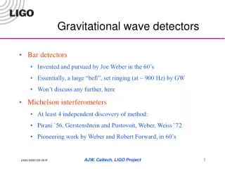
Livingston, LA (L1 4km) ~1 hour from New Orleans LIGO: Laser Interferometer Gravitational-wave Observatory Hanford Nuclear Reservation, Eastern Washington • Interferometers are aligned to be as close to parallel to each other as possible • Observing signals in coincidenceincreases the detection confidence • Determine source location on the sky, propagation speed and polarization of the gravity wave
Laser A Michelson Interferometer Phase Shift ∝ Arm Length Ly Signal ∝ Laser Power dP/dϕ ∝ PBS x sin(ϕ)cos(ϕ) Lx Anti-Symmetric (Dark) Port P ∝ PBS x sin2(ϕ) Shot Noise dP ∝ sqrt(P) Poisson Statistics... optimum
initial LIGO Science Requirement Promised Sensitivity to the NSF for the 1st Generation Detectors. --- hrms ~ 10-21 (hrms ~ h(f)*sqrt(f))
Laser A Michelson Interferometer Phase Shift ∝ Arm Length Ly Signal ∝ Laser Power dP/dϕ ∝ PBS x sin(ϕ)cos(ϕ) Lx Anti-Symmetric (Dark) Port P ∝ PBS x sin2(ϕ) Shot Noise dP ∝ sqrt(P) Poisson Statistics... optimum
High Power Limit #1:Opto-Mechanical Angular Instability Torque for single mirror Torque in a Fabry-Perot Cavity Stable J.A. Sidles and D. Sigg, PLA (2006) • Unstable in (5) Mirror Basis: increasing feedback gain fails • Change to Opto-Mechanical basis to provide conditional stability Unstable E. Hirose, K. Kawabe, D. Sigg, RA, and P.R. Saulson, App. Optics (2010) K.A. Dooley, L. Barsotti, M.Evans, RA, in prep (2012)
High Power Limit #2:Thermal Loading thermal distortion -> imperfect contrast ~few ppm absorption =>thermal distortions 15 kW 10 W W. Z. Korth, K. Izumi, K. Arai, RA, in prep (2012)
fPR ~ 2 Hz Enhanced LIGO Apply heating beam to make compensating lens 40 kW Power Recycling fFP ~ 100 Hz 35 W Optical Filter Cavity Baseband (homodyne) readout N. Smith, et al., Opt. Lett. (2012) 12 T. Fricke, N. Smith, R. Abbott, RA, et al.,CQG (2012)
Enhanced LIGO Performance Angular Control Noise 2x improvement
Timeline of GW Detectors 2nd Gen Interferometers 20NN 1970 1980 1990 2000 2010 2020 Caltech 40m ? ? ? ? 1st Tabletop Interferometer (Forward, Malibu) 1st Bar Detectors (Weber) km scale Interferometers (Japan, U.S., Germany, Italy) km scale Interferometers @ design sensitivity Interferometer Concept (Weiss, MIT)
Advanced LIGO x10 better amplitude sensitivity ⇒x1000rate=(reach)3 ⇒ 1 day of Advanced LIGO >> 1 year of Initial LIGO
Anatomy of the Interferometer Performance • Newtonian gravity noise • (a.k.a. Gravity Gradients) • Filtered Seismic • Silica Suspension Thermal Noise • Mirror Coating Thermal • Quantum Noise: Radiation Pressure / Shot Noise initial LIGO (2007) Advanced LIGO 2015 16
OUTLINE • Gravitational Waves and the Past • The LIGO Detectors • The Global Network and the Indian Possibility • The Future of GW Detectors & Observations
A Future GW Detector Network 25 29 10 22 39 36 21 light-speed travel time [ms]
Single Detector Response quadrature sum + polarized x polarized
Worldwide network needed for sky localization as well as polarization extraction: • Move 1 of 2 Hanford interferometers to the south. • Australian bid expired last year for budget reasons. • Indian team coming together: experimentalists, large project experience. Good indications from high level funding officials. • RA lab tours in August • Multiple visits by senior LIGO scientists to India • Preliminary go-ahead by NSF to pursue LIGO-India • LIGO Lab: go ahead. LIGO + Virgo LIGO + Virgo + India 20
OUTLINE • Gravitational Waves and the Past • The LIGO Detectors • The Global Network and the Indian Possibility • The Future of GW Detectors & Observations
Thermal Noise of a Mirror Reflectivity /Transmissivity Inertial Guidance Litton (1979) Ring Laser Gyro Ta2O5 Ion Beam Sputtered Mirror Coatings SiO2
Thermal Noise of a Mirror Single Damped Harmonic Oscillator Fluctuation-Dissipation Theorem Callen and Welton, Phys. Rev. (1951) Q = 104 Q = 108 Mirror Surface Thermal Fluctuations Yuri Levin, PRD (1998) Hong, Yang, Gustafson, RA, and Chen, PRD (2012)
Thermal Noise of a Mirror Why a ratio of 104 in dissipation? 2-level tunneling model R.O. Pohl, et al., Rev. Mod. Phys. (2002) • Nearly all high quality optical coatings use amorphous oxides. • Nearly all amorphous materials have a (low Q) large internal friction. W.A. Phillips, Rep. Prog. Phys. (1987)
Crystalline Mirror Coatings G. D. Cole, et al., Appl. Phys. Lett. (2010)
The Road to Noiseless Mirrors 300K design G. D. Cole, RA, F. Seifert, in prep. (2012) 120K Silicon: CTE = zero, High Thermal Conductivity Caltech IQIM JILA / PTB
Cryogenic LIGO Caltech Institute for Quantum Information and Mechanics JILA / PTB f ~4 GHz, Q ~105 , Nquanta < 1 Silicon etch process from O. Painter @ Caltech for ground state cooling Monolithic Silicon Suspension Requires switching the laser technology: 1064 nm => 1550 nm
Anatomy of the interferometer performance • Newtonian gravity noise • (aka Gravity Gradients) • Filtered Seismic • Silica Suspension Thermal Noise • Mirror Coating Thermal • Quantum Noise • Radiation Pressure • Shot Noise initial LIGO (2007) 30
What about this Quantum noise? Shot Noise Picture: Poisson statistics govern arrival time of photons at the photodetector. Also arrival times at the test mass (radiation pressure). Photodetector Vacuum Photon Picture:Losses couple the fluctuating vacuum field to the interferometer. Noise is a beat between the amplitude of the vacuum field and the local field (field at the dark port or field at the test mass). 31
Circumventing Usual Quantum Noise Squeezed Vacuum Vacuum Carrier Field Braginsky, Vorontsov and Thorne, Science (1980) C. M. Caves, PRD (1981) Wu, Kimble, Hall, Wu, PRL (1986)
Squeezed Interferometers Caltech 40m prototype 30% reduction GEO Squeezer (Hannover) K. Goda, et al., Nature Physics (2008) LIGO, Nature Physics (2011) Caltech 40m
Squeezed Light in Action: LIGO 4km Squeezed Light Injection Table Optical Parametric Oscillator (from ANU) Installed at LIGO Hanford throughout 2011
Squeezed Light in Action: LIGO 4km from L. Barsotti
Caltech 40m prototype Initial LIGO Enhanced LIGO Advanced LIGO 3rd Generation Instruments
Summary • The Advanced LIGO Detectors are on track for a 2014-2015 Science Run. • The Global Network of 2nd Generation detectors is coming together in the next 5-10 years. • Recent developments make the future potential bright. • We have never before been closer to GW Astrophysics.