Download
1 / 19
200 likes | 261 Views
This project focuses on designing an Acousto-Optic Tunable Filter (AOTF) using an all-fiber spectrometer setup. The AOTF, based on PZT technology, enables precise frequency control for various applications like infrared imaging and spectral analysis. The system integrates components such as light sources, photodetectors, and microcontrollers. Results include successful VCO control with some heat issues that need further investigation.

E N D
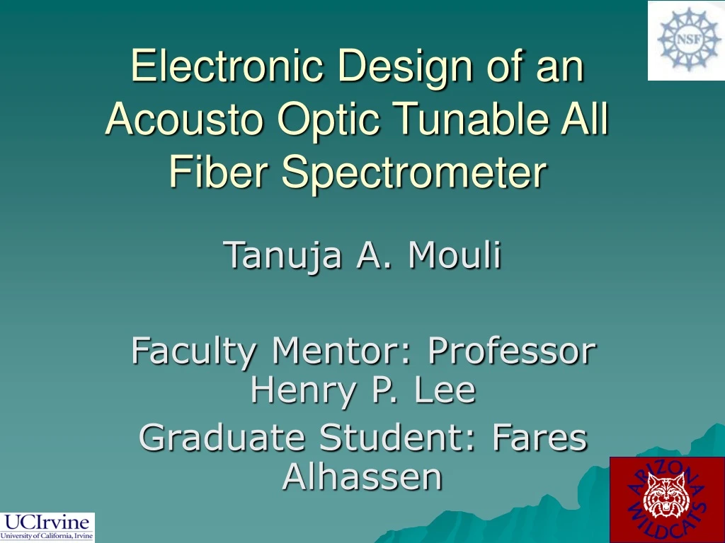
Electronic Design of an Acousto Optic Tunable All Fiber Spectrometer Tanuja A. Mouli Faculty Mentor: Professor Henry P. Lee Graduate Student: Fares Alhassen
The Project: Big Picture Unknown Wavelength
Acousto Optic Tunable Filter (AOTF) Metal Frame Optical Fiber PZT
AOTF: The PZT (Piezo Electric Tansducer) • Aluminum cone is attached to PZT disk • When AC voltage is applied, the cone vibrates up and down CONE AC PZT
The AOTF Acoustic wave RF PZT and horn (Piezo Electric Transducer) • When PZT vibrates, it creates a micro acoustic wave • Tunable filter is created by changing the frequency of PZT
AOTF: Notch Filter • Acts to pass wide range of frequencies • While attenuating narrow band of frequencies
AOTF PZT Aluminum Cone
Why use AOTF? • AOTF is easily tuned and can be controlled electronically • Optic fibers have low insertion power loss • Original spectrometer used costs 30K • Spectrometer built with AOTF will be low cost ($100), compact and portable
Common Applications • detect chemical compounds • particle sizes • Vibration • acoustic waves • electric field • fluid flow and temperature
Spectrometric Applications • Broadband Infrared (BBIR) • Tunable Camera Filter (TCF) • Portable Optical Spectra Analyzer (POSA)
The Design of the Spectrometer Light Source AOTF Photodetector (PD) RF Amplifier Current –to- Voltage Conversion VCO Microcontroller Output Data
Schematic: Microcontroller Connection with VCO 1. Press button once 2. Press button again 1V 2V 3V 4V
Final Circuit VCO C-V converter MCU
Problems and Solutions • VCO purchased (part #SN54LS624) did not output a clean sinusoidal. • A different VCO was used (MAX038) • When MAX038 was connected to microcontroller, the VCO gets hot
Results/Conclusion • Successfully controlled VCO • Need to work on why VCO gets hot. • Controlled C-V converter • Could not view output data
Said M. Shokair Dr. Henry P. Lee Fares Alhassen Patrick Chan Kevin Edmonds UROP UCI IM-SURE Acknowledgements
ANY QUESIONS?