Download
1 / 19
210 likes | 533 Views
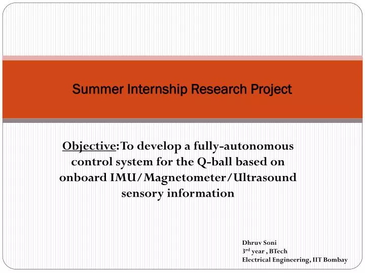
Summer Internship Research Project. Objective : To develop a fully-autonomous control system for the Q-ball based on onboard IMU/Magnetometer/Ultrasound sensory information. Dhruv Soni 3 rd year , BTech Electrical Engineering, IIT Bombay. Localization. Pitch/Roll command. Position command.

E N D
Summer Internship Research Project Objective: To develop a fully-autonomous control system for the Q-ball based on onboard IMU/Magnetometer/Ultrasound sensory information DhruvSoni 3rdyear , BTech Electrical Engineering, IIT Bombay
Localization Pitch/Rollcommand Position command Q-ball. PID LQR Pitch/Rollobserved Filter IMU Position observed Opti-track
Localization Pitch/Rollcommand Position command Q-ball. PID LQR Pitch/Rollobserved Filter IMU Position observed Opti-track Replace this with IMU-in the loop control block
Derivation of the kinematic equations for calculating the position of the Q-ball Navigation with respect to the inertial frame:
The accelerometers usually provide a measurement of specific force in a body fixed axis set, denoted by . In order to navigate, it is necessary to resolve the components of the specific force in the chosen reference frame. In the event that the inertial frame is selected, this may be achieved by pre-multiplying the vector quantity by the direction cosine matrix using: Where represents the turn rate of the body with respect to the i-frame as measured by the Gyroscopes.
Calculation of Rotational Matrix C To solve : f (t)= C(t) * f b(t) Rotational matrix C (t) is calculated by solving this differential equation On solving this differential equation we get Note: the solution will depend on initial attitude of the Q-ball
Simplifying Rotational Matrix C On applying Taylor’s expansion : Here B = δt * [ 0 -w_zw_yw_z 0 -w_xw_yw_x 0 ] And σ = | δt * sqrt{(w_x)2 + (w_y)2 + (w_z)2}|;
Deriving Position of Q-ball • f (t)= C(t) * f b(t) • Note that here δt is very small (order of m.sec) hence integration can be simplified to the following linear equations: • V (t + δt) = V(t) + δt * {f(t + δt) + g} here g= [0 0 9.8] • S (t + δt) = S(t) + δt * V(t + δt)
Experiment with Motors on (no propellers)(only noise signals) X calculated X optitrack
Experiment with Motors off (only noise signals) y calculated y optitrack
Experiment with Motors off (only noise signals) z calculated z optitrack
Sources of Error It was assumed that Initial attitude angles are zeroi.e. C(0) = [ 1 0 0 0 1 0 0 0 1 ]which may not be the case because even a slight tilt in initial orientation of q-ball, gives components of gravitational force which gets integrated over time in the algorithm can give us the exponential growth (as observed)
Experiment with initial tilt Accelerometer reading : Accel_x = 8.9478 Accel_y = 0.4572 Accel_z = -3.7881 Gyroscope reading : Gyro_x = 0 Gyro_y = 2.1817e-004 Gyro_z = 0
Modification in algorithm 1.> Velocity reset : Velocity of Q-ball is reset to zero at each sampling time 2.> Initial orientation of Q-ball is calculated to derive exact elements of C(0) matrix 3.> Constant gravitational acceleration vector is back transformed to body frame and subtracted from the Accelerometer reading
Results after Modifications(Motors on propellers off) X (Previous Algo) X (Modified Algo)
Results after Modifications Y (Previous Algo) Y (Modified Algo)
Results after Modifications Z (Previous Algo) Z (Modified Algo)
Next Steps • Test the algorithm for linear motion of Q-ball (smooth noise free motion , motors off) • Implement an Attitude determination algorithm for exact calculation of Rotational matrix in the localization algorithm