Download
1 / 25
250 likes | 271 Views
RF-TTC Joint News LEADE, June 2008. FAQs: Bunch Numbering Clocks Definition Clocks Frequency Range Clocks Generation Clocks Availability Flat Top Frequency changes with circumference Working with F40.ref and Orb1 Phase Shift with Temperature Status and evolution, Final tests

E N D
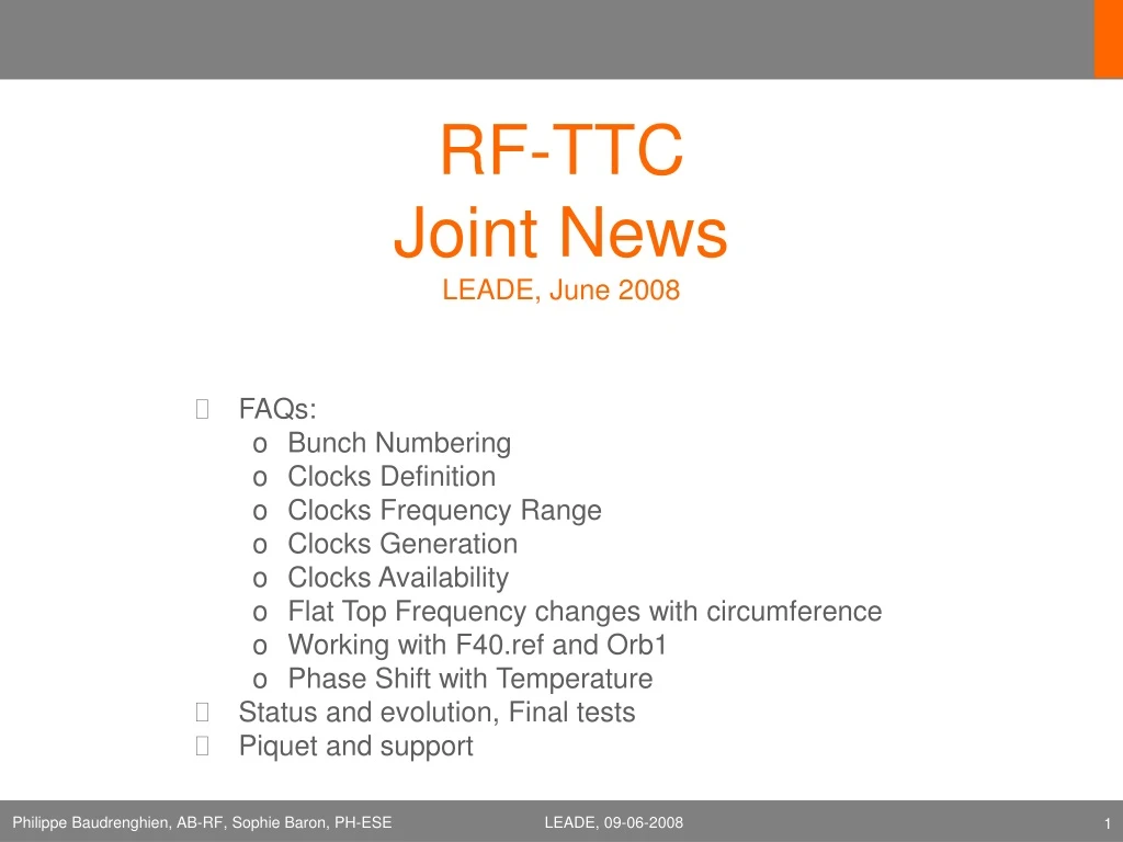
RF-TTC Joint NewsLEADE, June 2008 • FAQs: • Bunch Numbering • Clocks Definition • Clocks Frequency Range • Clocks Generation • Clocks Availability • Flat Top Frequency changes with circumference • Working with F40.ref and Orb1 • Phase Shift with Temperature • Status and evolution, Final tests • Piquet and support LEADE, 09-06-2008
AIM OF THIS PRESENTATION Trigger all questions, doubts, requests about RF signals and TTC… that may be did not come up yet, to avoid last minute surprises LEADE, 09-06-2008
FAQs LEADE, 09-06-2008
Bunch Numbering (reminder, see [1]) • Convention 1: The 400 MHz RF defines 35640 buckets, spaced by one RF period, and numbered from 1 to 35640 • Convention 2: Bucket 1 is the first bucket after the 3 ms long abort gap (defined from bucket 34442 to 35640) LEADE, 09-06-2008
Bunch Numbering Bucket 1 Abort Gap LEADE, 09-06-2008
Bunch Numbering • Convention 3:bunches in bucket 1 of the two rings collide in IP1 • FAQ • Q: Bunches in bucket 1 of both rings meet in IP1 (and IP5). Can this be changed ? • A: No…but if we want to have single bunch collisions in another IP we should inject in a different bucket of ring 2. For example for collision in IP2: Inject pilot in bucket 1 ring 1, and pilot in bucket 1 + 35640/4 = 8911 ring 2 . By delaying the ring 2 injection bucket by ¼ turn we displace the collision point by 1 octant LEADE, 09-06-2008
Commissioning Bunch Numbering. Phase A1: 1st turn, pilot [2] Label Bucket 1 Beam 1 • RF sets all its dividers (cogging) to offset 0 (ring 1) • Inject a single bunch pilot from SPS in ring 1 • By definition: This pilot is in bucket 1 • Get the pilot to make a few turns • EXP adjust delay in the BC1 and Orbit1 received. Must be done by various EXP as RF has only 1 signal for all EXP • Label Bucket 1 Beam 2. Repeat the above for beam 2 • Problem: Convention 3 is NOT respected. Bunches in bucket 1 must collide in IP1 -> we must rotate ring 2 with respect to ring 1 • BI or EXP measures the time difference of passages of the 2 pilots (ring 1 vs ring 2) In IP1 (or another IP) • The RF adjusts the cogging ring 2 thereby changing the collision point of the 2 pilots on next injection -> repeat until collision in IP1 (within +-1.25 ns). This adjustment does not change the position of the bunch ring 2 with respect to the Orbit2: When triggering on Orbit2 the bunch does not move. Conclusion: The RF will adjust the relative cogging of the 2 rings but we need a measurement from BI or EXP. This measurement best comes from a PU that sees both beams. LEADE, 09-06-2008
Clocks. Definition (Reminder) • Orbit1,2 (revolution frequency Frev1,2). For each ring: • The Orbit is a train of pulses, with one 5 ns long pulse per turn. This pulse “points” to bucket 1. The Orbit is obtained by dividing the RF by 35640 • At a given place in the machine, and at a given beam energy (that is fixed RF frequency) the delay between the pulse and the passage of a bunch in bucket 1 will be fixed from run to run. (Drift during the acceleration ramp due to the difference between signal transmission delay and the beam time of flight. For protons we have 6.5 ps/km, for ions 41.25 ps/km. Hopefully not a problem). • Bunch Clock1,2 (40 MHz1,2). For each ring: • The Bunch Clock is a square wave obtained by dividing the RF by 10. • At a given place in the machine, and at a given beam energy (RF frequency) the delay between the edge of the Bunch Clock and the passage of a bunch will be fixed from run to run • Jitter: • Orbit and Bunch Clocks are bunch-synchronous signals: Signal/bunch jitter is caused by transmission only (few tens ps) LEADE, 09-06-2008
Clocks. Definition • Reference Bunch Clock • The Ref Bunch Clock is a stable, constant frequency square wave at 40.078966 MHz (7 TeV proton, or another set collision energy) obtained by asynchronous division (1:10) of a 400 MHz Reference (400.789658 MHz). • On the flat top (7 TeV), but before physics starts, the two rings will be rephased onto the Ref Bunch Clock. • During physics, the delay between the edge of the Ref Bunch Clock and the passage of a bunch will be fixed from run to run. • Ref Bunch Clock jitter/stability • Absolute: It is generated from a commercial Agilent E4428C Low-Noise synthesizer (@ 400MHz). The 10 MHz ref comes from a GPS-disciplined Cristal Oscillator (Oscilloquartz OSA 5230). • Relative to bunch: We aim at less than 70 ps (10 dg@400 MHz) bunch to Ref Clock jitter. The resulting worst-case displacement of the collision point is 2 cm. (A bit more optimistic than [3]). LEADE, 09-06-2008
Clock Frequency Range (reminder) • Reference BC is fixed (depends on collision energy only) • BC1,2 and Orbit1,2 follow the RF during the acceleration ramp, but lock onto Ref BC before physics: • BC is 1/10 the RF frequency • Orbit is 1/35640 the RF frequency • RF frequency swing [4]: • Protons: from 400.788 790 MHz at injection (450 GeV) to 400.789 658 MHz at top energy (7 TeV) • Lead Ions: from 400.784 139 MHz at injection to 400.789 639 MHz at top energy LEADE, 09-06-2008
Clock Generation (updated) [5] LEADE, 09-06-2008
Electronics in SR4 Fiber Optic TX Generation of BCs and Orbits LEADE, 09-06-2008
Clock Availability • 1/35640 and 1/10 dividers (cogging) are resynchronized at each filling, once, before the PRE-INJECTION Plateau • During resynchronization the output signal disappears for ~1 ms (already the case) • Signal presence and validity is then guaranteed, until BEAM DUMP • After beam dump it is not excluded that the RF manipulate its equipment (switch a crate off/on) and signal may disappear. Experiments should make sure that no manual reset is needed in that case • Presence of signals is not guaranteed outside physics run due to maintenance needed on the RF equipment, or if basic control facilities are lacking. That applies in particular to shutdown periods. We will be of good will and do the best we can but… LEADE, 09-06-2008
FAQ [Will the frequency at flat top change?] • The circumference of the closed orbit will change of maximum 4mm => this should induce a variation of maximum 40 Hz of the flat top frequency LEADE, 09-06-2008
FAQ [Working with F40.ref during ramping] What will happen if we work with BCref and BC1 external orbit during the ramping? The orbit period will jump of 1 BC ‘tick’ about every 23ms = 73070 times! calculation made for a • theoretical linear ramping, • duration of 28 minutes • proton beam LEADE, 09-06-2008
FAQ [Phase shift with temperature] [6] Seasonal variations (over 6 months): ~ 10 ns for 18 km and 25°C outdoor variation ALICE: 14km => 8ns ATLAS: 14km => 8ns CMS: TUNNEL => probably < 1ns LHCb: 16km => 9ns Diurnal variations: ~270ps / 18km / 72 hours ~100ps/18km/12 hours (~ a run) ALICE: 210ps/72h, 80ps/12h ATLAS: 210ps/72h, 80ps/12h CMS: probably less than 100ps LHCb: 240ps/72h, 90ps/12h Will the absolute phase of the BC and orbit be sensitive to temperature variations? YES! Two different studies confirmed the same values. The shift should be the same for all the signals (as they are all in the same fibre) 2004-2005, Jan Troska, Sophie Baron, PH/ESE 2002, Abdelhalim Kelatma, Donat Stellfeld, AB/RF LEADE, 09-06-2008
Status and Evolution LEADE, 09-06-2008
Present Situation vs. Start-up • At present (June 6th) all clocks are generated from an RF at the fixed 400.789 000 MHz • No change for the Reference BC except for the RF frequency at 40.078 966 MHz (for 7 Tev collisions) • The other Bunch Clocks and Orbits: • will have a varying frequency, ramping from injection to collision (see above) • will be generated from a VCXO, locked on the beam, and trying to minimize the RF phase noise, as seen by the beam [3] • will have more absolute jitter as they are locked to the beam (max +- 70 ps) LEADE, 09-06-2008
TTC/BST [final tests] • BST cycles (typical machine modes sequences) • Being implemented very rapidly by AB/BI • Periodical mode changes triggered by a bit in the orbit counter (example: continuous sequence setup-injection-prepare ramp-ramp-flat top-squeeze-adjust-stable-beam dump warning-beam dump, with a change every 10 minutes) • The frequencies ramping will be operational during August. However, the ramping frequencies will be cleaner than during operation, because the jitter can be added only when the beam will be there. • We will try to organize a test session mixing machine modes and frequencies ramping LEADE, 09-06-2008
Support LEADE, 09-06-2008
Fiber Optic Monitoring • 3 RX per VME module • For Truelight Models • SIG_DETEC register = detection of RF output signal frequency in range 10 kHz-50.01 MHz • Reading of the measured frequency of the transmitted signal • We (AB/RF + CCR) want an interface to read these status/measurement LEADE, 09-06-2008
Piquet Service • During LHC operation • the AB/RF/FB section is responsible for the Clock transmission up to the RF outputs of the Fiber Optic RX located in the experiments • In case of problem the experiments must verify their modules first • They have 2 modules (with one spare input) + 1 hot spare, which should allow a quick replacement if required • If their modules are working fine but a signal is missing, contact the CCR • The CCR will decide to call the AB/RF/FB piquet Interventions of the RF piquet on experiments sites should be rare • This Piquet Service will be in operation shortly before start-up • In the meantime (commissioning) problems should be reported to Sophie LEADE, 09-06-2008
SUPPORT [Information channels] • Mailing lists are being set up • RF-users: for the RF operators to inform the RF users about interventions or problems on the system. This list will remain short (a few persons per experiments), and is moderated by Sophie Baron for the moment. • BST-users: for the BST operators to inform their users about interventions or problems on the system. Short list as well. Moderated by Sophie Baron as well for the moment. • DIP for status monitoring: • Directly used by the CCR/piquet by remotely logging on AB gateway • Indirectly used by the experiments: • No direct access • A web page will be set on this gateway to display general information • Status of the reception at all the reception points • Quality of the signal at the CCR support crate • Daily phase shift • Orbit synchronization (orbit period in terms of BC) • Training: • Configuration sessions: do not hesitate to contact Sophie if you need some training on the RF_Rx or RF2TTC modules. • RF-TTC users meeting to be organized during the summer. Please send us any (tricky) question you may have about timing!!! Philippe.Baudrenghien@cern.ch, Sophie.Baron@cern.ch • Documentation: • Web Pages: http://ttc-upgrade.web.cern.ch/ttc-upgrade/ • RF_Rx on EDMS: eda-01382 LEADE, 09-06-2008
References [1] LHC Fast Timing, Generation and Distribution, P. Baudrenghien, Leade meeting, May 7, 2007 [2] Bunch Numbering, P. Baudrenghien, LHCCWG meeting, March 11, 2008 [3] Position of the LHC Luminous Region, P. Baudrenghien, General Tracker Meeting, Dec 5th, 2001 [4] The LHC Radio-Frequency Swing, P. Baudrenghien, Leade meeting, Dec 15th, 2003 [5] TTC System Upgrade, S. Baron, Nov 24th, 2005, edms 628545 [6] Asservissement en Phase d’une Liaison Optique, 2002, Abdelhalim Kelatma, Donat Stellfeld LEADE, 09-06-2008
RF-TTC users meeting preparation Try to generate questions, doubts, worries in your own experiment Please transmit them to us!!! Philippe.baudrenghien@cern.ch Sophie.baron@cern.ch THANKS! LEADE, 09-06-2008