Download
1 / 27
270 likes | 305 Views
Learn about logic instructions, shift and rotate operations to manipulate bit patterns, clear, set, and examine bits. Understand AND, OR, XOR, NOT, TEST instructions and their effects on flags. Explore efficient machine code examples.

E N D
Lecture 5 Program Logic and Control (Boolean Operation Shift & Rotate Instructions)
Lecture Outline • Introduction • Logic Instructions • AND, OR, XOR Instructions • NOT Instruction • TEST Instruction • Shift Instructions • The SHL Instruction • The SHR Instruction • Rotate Instructions • The ROL Instruction • The ROR Instruction Logic Instructions 1
Introduction • Logic, shift, and rotate instructions can be used to change the bit pattern in a byte or word. • The ability to manipulate bits is generally absent in high-level languages (except C) and is an important reason for programming in assembly language. • It is used to check bit in a register or memory location, clear or set a register contents Logic Instructions 2
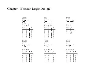
Logic Instructions • Logic instructions can be used to clear, set , and examine individual bits in a register or variable. • Logic instructions: • AND. • OR. • XOR. • NOT. • TEST. Logic Instructions 3
AND, OR, XOR Instructions a b a AND b a OR b a XOR b 0 0 0 0 0 0 1 0 1 1 1 0 0 1 1 1 1 1 1 0 10101010 10101010 10101010 AND 11110000 OR 11110000 XOR 11110000 = 10100000 = 11111010 = 01011010 Logic Instructions 4
register or memory location constant, register, or memory location AND, OR, XOR Instructions • Syntax AND destination, source OR destination, source XOR destination, source • The result of the operation is stored in the destination. • Memory-to-memory operations are not allowed. • Effect on flags: • SF, ZF, PF reflect the result. • AF is undefined. • CF = OF = 0. Logic Instructions 5
AND, OR, XOR Instructions • One use of AND, OR, and XOR is to selectively modify the bits in the destination. • To do this, we construct a source bit pattern known as a mask. • The mask bits are chosen so that the corresponding destination bits are modified in the desired manner when the instruction is executed. • To choose the mask bits, we make use of the following properties: • b AND 1 = b • b OR 0 = b • b XOR 0 = b • b AND 0 = 0 • b OR 1 =1 • b XOR 1 = ~b where b represent a bit (0 or 1). Logic Instructions 6
AND, OR, XOR Instructions • From these, we may conclude that: • The AND instruction can be used to clear specific destination bits while preserving the others. (0 mask bit clears - 1 mask bit preserves). • The OR instruction can be used to set specific destination bits while preserving the others. (1 mask bit sets - 0 mask bit preserves). • The XOR instruction can be used to complement specific destination bits while preserving the others. (1 mask bit complements - 0 mask bit preserves). Logic Instructions 7
AND, OR, XOR Instructions • Clear the sign bit of AL while leaving the other bits unchanged? AND AL, 7Fh (01111111) • Set the msb & lsb of AL while preserving the other bits? OR AL, 81h (10000001) • Change the sign bit of DX? XOR DX, 8000h (10000000) Logic Instructions 8
AND, OR, XOR Instructions • Convert an ASCII digit to a number? Character code 0 00110000 1 00110001 : : 9 00111001 AND AL, 0Fh Logic Instructions 9
AND, OR, XOR Instructions • Convert the lowercase character in DL to uppercase? Character code character code a 01100001 A 01000001 b 01100010 B 01000010 : : : : z 01111010 C 01011010 AND DL, 0DFh (01001101) Logic Instructions 10
Three bytes machine code Two bytes machine code (efficient) Two bytes machine code (efficient) AND, OR, XOR Instructions • Clear AX? MOV AX, 0 or SUB AX, AX or XOR AX,AX • Clear A? MOV A, 0 (memory location) Logic Instructions 11
AND, OR, XOR Instructions • Test CX for zero? OR CX, CX CX is unchanged but if CX = 0 then ZF = 1. It can be used as an alternative to CMP CX,0 Logic Instructions 12
NOT Instruction a NOT a 0 1 1 0 NOT 10101010 = 01010101 Logic Instructions 13
NOT Instruction • The NOT instruction performs the one’s complement operation on the destination. • Syntax: NOT destination • There is no effect on the status flags. • Complement the bits in AX? NOT AX Logic Instructions 14
TEST Instruction • The TEST instruction performs an AND operation of the destination with the source but does not change the destination contents. • The purpose of the TEST instruction is to set the status flags. • Syntax: TEST destination, source • Effect on flags: • SF, ZF, PF reflect the result. • AF is undefined. • CF = OF = 0. Logic Instructions 15
TEST Instruction • The TEST instruction can be used to examine individual bits in an operand. • The mask should contain: • 1’s in the bit positions to be tested. • 0’s elsewhere. • Jump to BELOW if AL contains an even number? TEST AL,1 JZ BELOW Logic Instructions 16
Introduction to shift and rotate instructions • The shift and rotate instructions shift the bits in the destination operand by one or more positions either to the left or right. • For a shift instruction, the bits shifted out are lost. • These instructions can be used to multiply and divide by powers of 2.(shift left to multiply and shift right to divide by 2) • For a rotate instruction, bits shifted out from one end of the operand are put back into the other end. Shift & Rotate Instructions 17
register or memory location SHIFT Instructions • Shift instructions: • SHL. • SHR. • Syntax: Opcode destination, 1 Opcode destination, CL ; where CL contains N • Effect on flags: • SF, PF, ZF reflect the result. • AF is undefined. • CF = last bit shifed out. • OF = 1 if the result changes sign on last shift. Shift & Rotate Instructions 18
0 CF 7 6 5 4 3 2 1 0 0 CF 15 14 13 12 11 10 9 8 7 6 5 4 3 2 1 0 The SHL Instruction • The SHL (shift left) instruction shifts the bits in the destination to the left. • SHL destination, 1 A 0 is shifted into the rightmost bit possition and the msb is shifted into CF. • SHL destination, CL; where CL contains N N single left shifts are made. The value of CL remains the same. Shift & Rotate Instructions 19
The SHL Instruction - Multiplication by SHL • A left shift on a binary number multiplies it by 2. • Ex. if AL contains 5d = 00000101b A left shift gives 10d = 00001010b Another left shift gives 20d = 00010100 • When we treat left shifts as multiplication, overflow may occur. • For 1 left shift, CF & OF accurately indicate unsigned and signed overflow, respectively. • Overflow flags are not reliable indicators for a multiple left shift. Ex. SHL BL, CL ; where BL = 80h and CL = 2 CF = OF = 0 even though both signed & unsigned overflow occurred. Shift & Rotate Instructions 21
0 7 6 5 4 3 2 1 0 CF 0 15 14 13 12 11 10 9 8 7 6 5 4 3 2 1 0 CF The SHR Instruction • The SHR (shift right) instruction shifts the bits in the destination to the right • SHR destination, 1 A 0 is shifted into the msb possition and the rightmost bit is shifted into CF. • SHR destination, CL ; where CL contains N N single right shifts are made. The value of CL remains the same. Shift & Rotate Instructions 22
1 0 0 0 1 0 1 0 00 1 0 00 1 0 10 7 6 5 4 3 2 1 0 CF 1 0 0 1 0 0 0 1 0 7 6 5 4 3 2 1 0 CF The SHR Instruction • Suppose DH contains 8Ah and CL contains 2. What are the values of DH and of CF after the instruction SHR DH, CL is executed? • DH before • SHR DH, CL • CF & DH After SAR (shift Arithmetic Right) instruction can also used instead of SHR Both have same machine codes Shift & Rotate Instructions 23
The SHR Instruction - Division by SHR • For even numbers, a right shift divides it by 2. • Ex. if AL contains 6d = 00000110b A right shift gives 3d = 00000011b • For odd numbers, a right shift halves it and rounds down to the nearest integer. • Ex. if AL contains 5d = 00000101b A right shift gives 2d = 00000010b • Use SHR to divide 65143 by 4, put the quotient in AX. MOV AX, 65143 ; AX has number MOV CL, 2 ; CL has number of right shifts SHR AX, CL ; divide by 4 Shift & Rotate Instructions 24
register or memory location Rotate Instructions • Rotate instructions: • ROL. • ROR. • Syntax: Opcode destination, 1 Opcode destination, CL ; where CL contains N • Effect on flags: • SF, PF, ZF reflect the result. • AF is undefined. • CF = last bit shifted out. • OF = 1 if the result changes sign on last shift. Shift & Rotate Instructions 25
CF 7 6 5 4 3 2 1 0 CF 15 14 13 12 11 10 9 8 7 6 5 4 3 2 1 0 The ROL Instruction • The ROL (rotate left) instruction shifts the bits in the destination to the left. • The msb is shifted into the rightmost bit and also into the CF. Shift & Rotate Instructions 26
7 6 5 4 3 2 1 0 CF 15 14 13 12 11 10 9 8 7 6 5 4 3 2 1 0 CF The ROR Instruction • The ROR (rotate right) instruction shifts the bits in the destination to the right. • The rightmost is shifted into the msb bit and also into the CF. Shift & Rotate Instructions 28