Download

1 / 21
210 likes | 231 Views
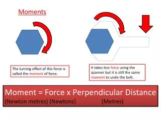
Moments. FORCE. Moment. The moment of a force is a measure of the tendency of the force to rotate the body upon which it acts. distance. FORCE. Terminology. = F. lever arm. pivot. = d. The distance must be perpendicular to the force. distance. FORCE. Moments Formula. = F. pivot.

E N D
FORCE Moment Themomentof a force is a measure of the tendency of the force to rotate the body upon which it acts.
distance FORCE Terminology = F lever arm pivot = d The distance must be perpendicular to the force.
distance FORCE Moments Formula = F pivot = d Moment M M = d x F
Rotation Direction In order to add moments, it is important to know if the direction is clockwise (CW) or counterclockwise (CCW). • CCW is positive • CW is negative
Right-Hand Rule Curl your fingers to match the direction of rotation. + Thumb is pointing . . . . Up = Positive Down = Negative Toward You = Positive Away from You = Negative counterclockwise
FORCE Right-Hand Rule THUMB POINTS TOWARD YOU POSITIVE
FORCE Right-Hand Rule THUMB POINTS AWAY FROM YOU NEGATIVE
¯ FORCE d= 9.0 in. Moment Calculations Wrench F = 20. lb M = d x F Use the right-hand rule to determine positive and negative. d= 9.0 in. = .75 ft M = -(20. lb x .75 ft) M = -15 lb-ft (15 lb-ft clockwise)
¯ FORCE d= 1.0 ft Moment Calculations Longer Wrench F = 20. lb M = d x F M = -(20. lb x 1.0 ft) M = -20. lb-ft
¯ FORCE d= 1.0 ft Moment Calculations L - Shaped Wrench F = 20. lb d= 3 in. = .25 ft M = d x F M = -(20. lb x .25 ft) M = -5 lb-ft 3 in.
¯ FORCE Moment Calculations Z - Shaped Wrench F = 20. lb d= 8 in. + 10 in. = 1.5 ft M = d x F M = -(20. lb x 1.5 ft) M = -30. lb-ft 9 in. 8 in. 10. in.
r = 50. cm + Moment Calculations Wheel and Axle d= r = 50. cm = 0.50 m M = d x F Use the right-hand rule to determine positive and negative. M = 100 N x 0.50 m M = 50 N-m F = 100 N
r = 50. cm 50.o 50.o Fy Moment Calculations Wheel and Axle Fy= Fsin50.° = (100. N)(.766) Fy = 76.6N d = r = 50. cm = 0.50 m M = d x Fy M = 76.6 N x 0.50 m M = 38 N-m F = 100. N
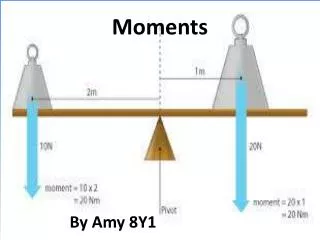
What is Equilibrium? ΣM = 0 M1 + M2 + M3 . . . = 0 The state of a body or physical system with an unchanging rotational motion. • Two cases for that condition: • Object is not rotating OR • Object is spinning at a constant speed • In either case rotation forces are balanced: Thesum of all moments about any point or axis is zero.
Moment Calculations See-Saw
¯ + d1= 4.0 ft d2= ? ft Moment Calculations ΣM = 0 M1 + M2= 0 Use the right-hand rule to determine positive and negative. M1 = -M2 d1 x F1= d2 x F2 25lb x 4.0ft - 40. lb x d2=0 100lb-ft = 40. lb x d2 See-Saw F2 = 40. lb F1 = 25 lb 40. lb 40. lb 2.5 ft = d2
dAB= 10.00 ft dAC= 3.00 ft Moment Calculations Loaded Beam Select A as the pivot location. Solve for RBy ΣM = 0 MB+ MC = 0 MB = -MC dABxRBy= dACx FC 10.00 ftx RBy= 3.00 ft x 35.0 lb 10.0 ft x RBy = 105 lb-ft C 10.00 ft 10.00 ft A B RBy = 10.5 lb RAy + RBy = 35.0 lb RAy = 35.0 lb – 10.5 lb= 24.5 lb FC = 35.0 lb RAy RBy
Moment Calculations Truss FB = 500. lb B Replace the pinned and roller supports with reaction forces. 12 ft RAx A C 24 ft 8 ft D dAC= 24 ft dCD= 8 ft dCB= 12 ft dAD= 32 ft RAy Fc = 600. lb RDy
Moment Calculations Truss Select A as the axis of rotation. Solve for RDY ΣM = 0 MD – MB – MC = 0 MD = MB + MC dAD x RDy= (dCBx FB) + (dACx FC) 32 ftx RDy= (12 ft x 500. lb) + (24 ft x 600. lb) RDy x 32 ft = 6000lb-ft + 14400lb-ft RDy x 32 ft = 20400lb-ft FB = 500. lb B 12 ft 12 ft RAx A C 8 ft 24 ft D 32 ft 32 ft dAC= 24 ft dCD= 8 ft dCB= 12 ft dAD= 32 ft RDY = 640 lb RAy Fc = 600. lb RDy