Download

1 / 20
200 likes | 350 Views
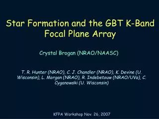
K- band Focal Plane Array. K band History. Science workshop determined efficiency improvements necessary for K Band: weather, observing requests, mapping programs.

E N D
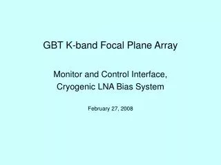
K- band Focal Plane Array
K band History • Science workshop determined efficiency improvements necessary for K Band: weather, observing requests, mapping programs. • Only enough funds for the receiver only, so the project was de-scoped to seven pixels that meets science objectives as specified in the science case. • $1.2 M Total • $0.19 M Parts • $0.2 M Contingency • $0.83 M Labor • The K band seven pixel focal plane array is the path finder instrument: a necessary first step and feasible considering time frame. • Seven pixel array construction complete December, 2009 • Production use by November, 2010.
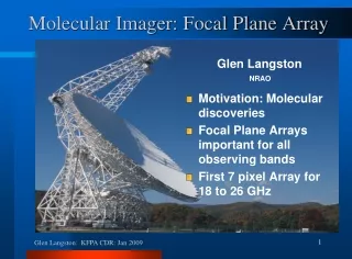
K band Focal Plane Array • Science Driver → Map NH3 • Polarized without Rotation • Seven Beams → Limited by IF system • 1.8 GHz BW → Limited by IF system • 800 MHz BW → Limited by Spectrometer
K-band FPA Deliverables • Frontend • Cryogenic Package for Seven Pixel Instrument • Seven Dual Circular Polarization K band Pixels • Modular Noise Calibration for each Pixel • Modular Downconverter for each Channel (14) • Monitor and Control Electronics • LO Distribution with Doubler for LO1A • Software • Package for Engineering M&C • Observing Software Manager • Data Analysis Pipeline • Cost per Pixel not including NRE. • $46,000 Parts (Dewar,EM parts, Isolator, HEMT Amp, WG parts, Noise Mod, IDM) • $2500 Labor Construction. • $2500 Software upgrades.
1. Initial 7 elements above 68% beam efficiency (illumination and spillover) 2. Expandable to as many as 61 elements 3. beam efficiency of outermost elements would drop to ~60%. 4. beam spacing = 3 HPBWs Focal Plane Coverage simulated beam efficiency vs. offset from center
GBT Beam Spatial Coverage/ Resolution GBT Aperture Spacing
Noise Temperature and Headroom Limited by Existing Cryogenic LNA Design Noise Temperature: 36 K max 18-26.5 GHz, 25 K over 75% of band P1dB Headroom: 30 dB when Tant = 300 K
Cosine Taper Corrugated Feed Horn Frequency Range: 18-26.5 GHz (17-27.5 GHz goal)
Feed Thermal Transition Isolators Phase Shifter OMT HEMT Noise Module Sliding Transition K Band Single Pixel
Two downconverters are needed to implement the IF multiplexing scheme. The second downconverter simply omits the latter mixing stage.
Future FPA Developments Wish List • Significantly enhanced spectrometer with this new array and existing IF system. • New digital I.F. distribution system. (Spectrometer and technology dependent). • Expanded focal plane array (perhaps at a different frequency: W band)