Download
1 / 24
240 likes | 263 Views
Responsibility Assignment Matrix (RAM) — Purpose. Ensure that all tasks are assigned to people Show levels of involvement of people to work. Linkage Between WBS and OBS. OBS. X. X. WBS. X. X. Responsibility Assignment Matrix. RASIC Method. SENIOR MANAGEMENT. TEAM MEMBER.

E N D
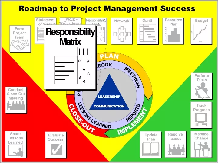
Responsibility Assignment Matrix (RAM) — Purpose • Ensure that all tasks are assigned to people • Show levels of involvement of people to work
Linkage Between WBS and OBS OBS X X WBS X X
Responsibility Assignment Matrix RASIC Method SENIORMANAGEMENT TEAMMEMBER SUPPORTSTAFF PROJECTMANAGER CUSTOMER MARKETING STUDY R I I A I I A S S S S S S S R/S S R I I I I A S S S I S IDENTIFY POTENTIAL MARKET IDENTIFY SURVEY POPULATION DEVELOP SURVEY TEST SURVEY ON SAMPLE FINALIZE SURVEY CONDUCT SURVEY COLLECT SURVEY ANALYZE DATA REPORT RESULTS AND SUGGESTION C C R R R R R R LEGEND R - RESPONSIBLEA - APPROVES - SUPPORT (DOES THE WORK)I - INFORMC - CONSULT
Guidelines • Team member names should be shown across the horizontal axis in the final matrix. • There should be only one R and one S for each activity if possible. • Every activity should have an R and an S. R/S for an activity is acceptable. • The project manager will have the majority of Rs. • The customer and senior management have the majority of As and Is.
Project Schedule — Purpose • Determine if requested completion date is possible. • Identify start and completion dates of all work. • Determine the controlling sequence of activities. • Provide data for resource allocation. • Track progress by providing a baseline.
Scheduling Step 1: Estimate Activity Durations
Estimating Techniques • Deterministic • Best Guess • Delphi (Consensus) • Probabilistic • Program Evaluation Review Techniques (PERT)
Scheduling Step 2: Determine Activity Sequence By Creating a Network Diagram
g a b c d e f h i j i b d e h a c j f g WBS/Network Diagram Linkage
Network Diagram Methods C A B J D F E G Arrow Diagram Method H I J C A B D E F G Precedence Diagram Method H I
Create a Network Diagram • A is the first activity • B, C and D are dependent on A • E and F are dependent on B • G is dependent on C • H is dependent on C and D • I is dependent on F and G • J is dependent on E, I, and H • J is the last activity
Precedence Diagram Method E B F I A C J G D H Logic Connection Activity
Scheduling Step 3: Calculate the Schedule Using Critical Path Method (CPM) Procedures
What’s is the Critical Path? • Riskiest path in a project • Path with the most important activities • Path with least slack • Path with least resistance • Path with longest duration • Path to Emerald City
What’s is the Critical Path? • Path with least slack • Path with longest duration
Determine the Critical Path • A = 2 weeks • B = 1 week • C = 3 weeks • D = 1 week • E = 4 weeks • F = 3 Weeks • G = 2 weeks • H = 1 week • I = 2 weeks • J = 1 week
Project X — Critical PathSolution E Activity Name Float Duration 2 4 3 7 5 9 ES EF LS LF B F 1 1 1 3 2 3 3 4 3 6 4 7 I G J A C 0 0 0 0 0 2 2 3 2 1 5 7 5 7 7 9 7 9 9 10 9 10 0 2 0 2 2 5 2 5 H D 3 5 1 1 2 3 7 8 5 6 8 9
Scheduling Step 4: Show the Schedule by Drawing Gantt and/or Milestone Charts
Enhanced Gantt Chart Jan Feb Mar April May June Task A Task B Task C Task D Task E Task F - Non-Critical - Slack/Float - Critical
Gantt Charts • Simple to construct • Easy to interpret • Good for management reporting
Project X — Gantt Chart Solution Time 1 2 3 4 5 6 7 8 9 10 Activity Duration 2 A B C D E F G H I J 1 3 1 4 3 2 1 2 1 - Non-Critical - Slack/Float - Critical
Develop a Project Schedule • Prepare a project schedule for the room you are going to paint.