Download
1 / 5
100 likes | 385 Views
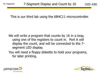
7-Segment Display and Count by 16. This is our third lab using the 68HC11 microcontroller. We will write a program that counts by 16 in a loop, using one of the registers to count in. Port A will display the count, and will be connected to the 7-segment LED display.

E N D
7-Segment Display and Count by 16 This is our third lab using the 68HC11 microcontroller. We will write a program that counts by 16 in a loop, using one of the registers to count in. Port A will display the count, and will be connected to the 7-segment LED display. You will need a floppy diskette to hold your programs, for later printing.
Lab Preparation A: – simp3v2.asm • Examine simp2v2.asm to determine how the LEDs are being controlled in the loop. • Determine the changes needed to modify the program, so that Port A will contain and display the contents of a register (bits 4,5,6 on pins 4,5,6). • Determine the changes needed to make your register count up by 16s. • Since you will be displaying only 3-bits (4,5,6) of an 8-bit number in the register, explain in your notebook, how counting by 16 will work and what it will show on the 7-segment LED. • During the lab, you will edit and modify a copy of simp2v2.asm to create count-16.asm. You will assemble count16.asm and download it into the MicroStamp board, for execution and testing.
MODIFIED simp2v2.asm **************************************************************** *file: simp2v2.asm *This program illustrates flashing PA6.. *Dr. Hoganson, 10/2/02 **************************************************************** org $e000 ;beginning of EEPROM (68HC811E2) rbase equ $0000 ;beginning of register/memory port_a equ rbase+0 ;port A is the first register h_sec equ $ffff ;delay loop value (about 1/2 second) **************************************************************** begin: ldaa #$04 ;value to disable timed interrupt staa $3f ;disables the timed interrupt lds #$ff ;set stack start loop: ldaa #$40 ;write logic high to PA6 (turn on LED) staa port_a ;$0 is location of Port A bsr delay clr port_a ;clear PortA bsr delay bra loop Continued next slide
MODIFIED simple2.asm **************************************************************** * delay loop subroutine **************************************************************** delay: ldy #h_sec ;delay loop (about 1/2 second) dloop: dey iny ;extra iny,dey add delay time dey bne dloop rts **************************************************************** org $fffe ;define the reset vector to point to start of program fdb begin ;begin is the start of the program
Part B: The Lab Record in your lab notebook, your observations for each of the following steps. • Wire the 68HC11 as we did in the last lab, with power and ground, and LEDs connected to Port A bits 4,5,6. • Wire three PortA outputs to the inputs to the decoder for the 7-segment display. Also wire a ground from one of the 7-seg displays. • Verify correct operation by running the demo program, but also checking the wiring to the 7-segment display. • Edit, assemble, download, and test your count16.s19 program, and verify correct operation. • You will need to save your program on your floppy diskette, and print out a listing of each program, which you will insert into your lab notebook.