Download
1 / 48
640 likes | 1.39k Views
Chapter 5 - Long-Distance Communication. Long-distance communication Sending signals long distances Oscillating signals Encoding data with a carrier Types of modulation Examples of modulation techniques Encoding data with phase shift modulation Hardware for data transmission

E N D
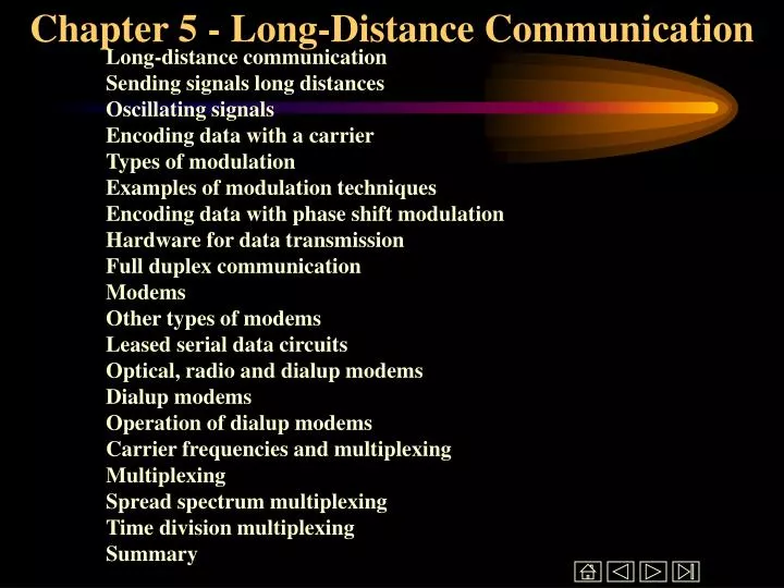
Chapter 5 - Long-Distance Communication Long-distance communication Sending signals long distances Oscillating signals Encoding data with a carrier Types of modulation Examples of modulation techniques Encoding data with phase shift modulation Hardware for data transmission Full duplex communication Modems Other types of modems Leased serial data circuits Optical, radio and dialup modems Dialup modems Operation of dialup modems Carrier frequencies and multiplexing Multiplexing Spread spectrum multiplexing Time division multiplexing Summary
Long-distance communication • Encoding used by RS-232 cannot work in all situations • Over long distances • Using existing systems like telephone • Different encoding strategies needed
Sending signals long distances • Electric current becomes weaker as it travels on wire • Resulting signal loss may prevent accurate decoding of data • Signal loss prevents use of RS-232 over long distances
Oscillating signals • Continuous, oscillating signal will propagate farther than electric current • Long distance communication uses such a signal, called a carrier • Waveform for carrier looks like: • Page 68 Figure 6.1 • Carrier can be detected over much longer distances than RS-232 signal
Encoding data with a carrier • Modifications to basic carrier encode data for transmission • Technique called modulation • Same idea as in radio, television transmission • Carrier modulation used with all types of media - copper, fiber, radio, infrared, laser
Types of modulation • Amplitude modulation - strength, or amplitude of carrier is modulated to encode data • Frequency modulation - frequency of carrier is modulated to encode data • Phase shift modulation - changes in timing, or phase shifts encode data
Examples of modulation techniques • Amplitude modulation: • Page 69 Figure 6.2 • Phase shift modulation: • Page 69 Figure 6.3
Encoding data with phase shift modulation • Amount of phase shift can be precisely measured • Measures how much of sine wave is "skipped" • Each phase shift can be used to carry more than one bit; in example, four possible phase shifts encode 2 bits: • 00 - no shift • 01 - 1/4 phase • 10 - 1/2 phase • 11 - 3/4 phase • Thus, each phase shift carries 2 bits • Data rate is twice the baud rate
Hardware for data transmission • Modulator encodes data bits as modulated carrier • Demodulator decodes bits from carrier • Data transmission requires modulator at source and demodulator at destination
Full duplex communication • Most systems provide for simultaneous bi-directional, or full duplex, transmission • Requires modulator and demodulator at both endpoints: • Page 71 Figure 6.4 • Long-distance connection is called 4-wire circuit • Modulator and demodulator typically in single device called a modem (modulator/demodulator)
Modems • If external to computer, RS-232 can be used between modem and computer • If internal, direct bus connection used • Can also be rack-mounted
Other types of modems • ISDN modem • Cable modem • Cable modem with coax connector for cable and 10Base-T connector
Leased serial data circuits • Organizations often include 4-wire circuits in network • Within a site - on a campus - organization can install its own 4-wire circuits • Telephone company supplies off-campus wires • Telephone cables have extra wires (circuits) for expansion • Telephone company lease right to use wires to organization • Organization uses modems for data transfer • Called serial data circuit or serial line • Operates in parallel with (but not connected to) telephone circuits
Optical, radio and dialup modems • Modems used with other media in addition to dedicated data circuits • Special form of encoding/decoding transducers that use modulation for data encoding • Glass - data encoded as modulated light beam • Radio - data encoded as modulated radio signal • Dialup - data encoded as modulated sound • Dialup modem connects to ordinary phone line
Dialup modems • Circuitry for sending data • Circuitry to mimic telephone operation • Lifting handset • Dialing • Replacing handset (hanging up) • Detect dial tone • Full duplex on one voice channel • Different carrier frequencies for each direction • Filters eliminate interference
Operation of dialup modems • Receiving modem waits for call in answer mode • Other modem, in call mode: • Simulates lifting handset • Listens for dial tone • Sends tones (or pulses) to dial number • Answering modem: • Detects ringing • Simulates lifting handset • Sends carrier • Calling modem: • Sends carrier • Data exchanged
Carrier frequencies and multiplexing • Multiple signals with data can be carried on same medium without interference • Allows multiple simultaneous data streams • Dialup modems can carry full-duplex data on one voice channel • Example - multiple TV stations in air medium • Each separate signal is called a channel
Multiplexing • Carrying multiple signals on one medium is called multiplexingPage 74 figure 6.6 • Frequency division multiplexing (FDM) achieves multiplexing by using different carrier frequencies • Receiver can "tune" to specific frequency and extract modulation for that one channel • Frequencies must be separated to avoid interference • Only useful in media that can carry multiple signals with different frequencies - high-bandwidth required
Spread spectrum multiplexing • Spread spectrum uses multiple carriers • Single data stream divided up and sent across different carriers • Can be used to bypass interference or avoid wiretapping
Time division multiplexing • Time division multiplexing uses a single carrier and sends data streams sequentially • Transmitter/receiver pairs share single channel • Basis for most computer networks used shared media - will give details in later chapters
Summary • Long-distance communications use carrier and modulation for reliable communication • Modulator encodes data and demodulator decodes data • Can use amplitude, frequency or phase shift modulation • Multiple transmitter/receiver pairs can use multiplexing to share a single medium
Chapter 6 - Packets, Frames and Error Detection Shared communication media Packets Motivation Dedicated network access Packet switching access Time-division multiplexing Time-division multiplexing - example Packets and frames Frame formats Defining the framing standard Frame format Packet framing Framing in practice Transmitting arbitrary data Data stuffing
Chapter 6 - Contd Byte stuffing Byte stuffing example Transmission errors Error detection and correction Parity checking Parity and error detection Limitations to parity checkingAlternative error detection schemes Checksums Implementing checksum computation Limitations to checksums Cyclic redundancy checks Hardware components CRC hardware Error detection and framesSummary
Shared communication media • Most network use shared media which interconnect all computers • However - only one source can transmit data at a time
Packets • Most networks divide into small blocks called packets for transmission • Each packet sent individually • Such networks are called packet networks or packet switching networks
Motivation • Coordination - helps transmitter and receiver determine which data have been received correctly and which have not • Resource sharing - allows multiple computers to share network infrastructure • Networks enforce fair use - each computer can only send one packet at a time
= 11.9 minutes 5x106 bytes * 8 bits/byte Dedicated network access • 5MB file transferred across network with 56Kbps capacity will require 12 minutes: 60 secs/minute * 56x103 bits/second • All other computers will be forced to wait 12 minutes before initiating other transfers
1000 bytes * 8 bits/byte = .143 seconds Packet switching access • If file is broken into packets, other computers must only wait until packet (not entire file) has been sent • From previous example, suppose file is broken into 1000 byte packets • Each packet takes less than .2 seconds to transmit: 56x103 bits/second • Other computer must only wait .143 seconds before beginning to transmit • Note: • If both files are both 5MB long, each now takes 24 minutes to transmit • BUT if second file is only 10KB long, it will be transmitted in only 2.8 seconds, while 5MB file still takes roughly 12 minutes
Time-division multiplexing • Dividing data into small packets allows time-division multiplexing • Each packet leaves the source and is switched onto the shared communication channel through a multiplexor • At the destination, the packet is switched through a demultiplexor to the destination
Packets and frames • Packet is a generic term that refers to a small block of data • Each hardware technology uses different packet format • Frameor hardware frame denotes a packet of a specific format on a specific hardware technology
Frame formats • Need to define a standard format for data to indicate the beginning and end of the frame • Header and trailer used to ``frame'' the data
Defining the framing standard • Can choose two unused data values for framing • E.g., if data is limited to printable ASCII, can use • ``start of header'' (soh) • ``end of text'' (eot) • Sending computer sends soh first, then data, finally eot • Receiving computer interprets and discards soh, stores data in buffer and interprets and discards eot
Frame format Page 84 Figure 7.3
Framing in practice • Incurs extra overhead - soh and eot take time to transmit, but carry no data • Accommodates transmission problems: • Missing eot indicates sending computer crashed • Missing soh indicates receiving computer missed beginning of message • Bad frame is discarded
Transmitting arbitrary data • Suppose system can't afford to reserve two special characters for framing • E.g., transmitting arbitrary 8-bit binary data • soh and eot as part of data will be misinterpreted as framing data • Sender and receiver must agree to encode special characters for unambiguous transmission
Data stuffing • Bit stuffing and byte stuffing are two techniques for inserting extra data to encode reserved bytes • Byte stuffing translates each reserved byte into two unreserved bytes • For example, can use esc as prefix, followed by x for soh, y for eot and z for esc: • Page 86 Figure 7.4
Byte stuffing • Sender translates each reserved byte into the appropriate encoding pair of bytes • Receiver interprets pairs of bytes and stores encoded byte in buffer • Data still framed by soh and eot • Page 86 Figure 7.5
Transmission errors • External electromagnetic signals can cause incorrect delivery of data • Data can be received incorrectly • Data can be lost • Unwanted data can be generated • Any of these problems are called transmission errors
Error detection and correction • Error detection - send additional information so incorrect data can be detected and rejected • Error correction - send additional information so incorrect data can be corrected and accepted
Parity checking • Parity refers to the number of bits set to 1 in the data item • Even parity - an even number of bits are 1 • Odd parity - an odd number of bits are 1 • A parity bit is an extra bit transmitted with a data item, chose to give the resulting bits even or odd parity • Even parity - data: 10010001, parity bit 1 • Odd parity - data: 10010111, parity bit 0
Parity and error detection • If noise or other interference introduces an error, one of the bits in the data will be changed from a 1 to a 0 or from a 0 to a 1 • Parity of resulting bits will be wrong • Original data and parity: 10010001+1 (even parity) • Incorrect data: 10110001+1 (odd parity) • Transmitter and receiver agree on which parity to use • Receiver detects error in data with incorrect parity
Limitations to parity checking • Parity can only detect errors that change an odd number of bits • Original data and parity: 10010001+1 (even parity) • Incorrect data: 10110011+1 (even parity!) • Parity usually used to catch one-bit errors
Alternative error detection schemes • Many alternative schemes exist • Detect multi-bit errors • Correct errors through redundant information • Checksum and CRC are two widely used techniques
Checksums • Sum of data in message treated as array of integers • Can be 8-, 16- or 32-bit integers • Typically use 1s-complement arithmetic • Example - 16-bit checksum with 1s complement arithmetic • Page 89 Figure 7.6
Implementing checksum computation • Easy to do - uses only addition • Fastest implementations of 16-bit checksum use 32-bit arithmetic and add carries in at end • Can also speed computation by unrolling loop and similar optimizations
Limitations to checksums • May not catch all errors • Page 90 Figure 7.7
Cyclic redundancy checks • Consider data in message as coefficients of a polynomial • Divide that coefficient set by a known polynomial • Transmit remainder as CRC • Good error detection properties • Easy to implement in hardware
Summary • Computer networks divide data into packets • Resource sharing • Fair allocation • Hardware frames are specific to a particular hardware network technology • Each frame has a specific format that identifies the beginning and end of the frame • Error detection and correction is used to identify and isolate transmission errors