Download
1 / 50
540 likes | 922 Views
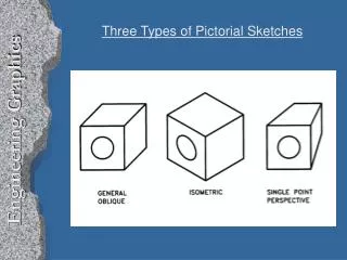
Engineering Graphics. A few highlights. See “A Brief Introduction to Engineering Graphics” in the Resources section of the ME2011 web site See Q01 on the Assignments page for what you need to know for the graphics quiz. Documenting a part requires. 1. SHAPE 2. SIZE 3. MATERIAL 4. TOLERANCE

E N D
Engineering Graphics A few highlights
See “A Brief Introduction to Engineering Graphics” in the Resources section of the ME2011 web siteSee Q01 on the Assignments page for what you need to know for the graphics quiz
Documenting a part requires... 1. SHAPE 2. SIZE 3. MATERIAL 4. TOLERANCE 5. FINISH
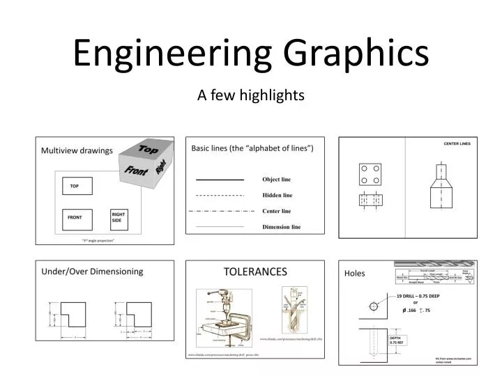
Top Right Front Multiview drawings TOP RIGHT SIDE FRONT “3rd angle projection”
Basic lines (the “alphabet of lines”) Object line Hidden line Center line Dimension line
FRONT FIND THE MISTAKES!
Interpreting Center Lines Enough Info? Enough Info?
OR THIS Centerlines imply symmetry, NOT revolution per se
HERE, ONLY 2 VIEWS NEEDED (Correct drawing)
A A SECTIONS YES NO
DIMENSIONING 1. SHAPE2. SIZE3. MATERIAL4. TOLERANCE AND FINISH
5 5 3 3 2 3 5 5 Dimensioning rules: …find the mistakes.
6.0 6.0 Design Detail½” thick aluminum block Which is more expensive: A or B and why? A B 4.0 4.1 What if A was 3.9 in width?
6 6 2 4 2 2 6 6 Dimensioning Choices& Design Intent If change width of block to 8, what happens to the hole location? B A
TOLERANCES www.efunda.com/processes/machining/drill.cfm www.efunda.com/processes/machining/drill_press.cfm
½ inch drill bit: +/- .0040 ½ inch reamer: +.0003, -.0000
Tolerance stack-up What is min and max height of stack? 14.7515.25 ? 3.0 ± .05 5 high stack
Tolerance Stacking Ans: +/- 0.3 What’s the tolerance (+/-) on dimension x?
.626 .623 .625 .622 • Will all shafts fit into all holes? • A = yes, B = no • What is maximum clearance? • A = .001, B = .002, C = .003, D = .004 Holes and shafts hole shaft .623 .622 .626 .625
{ A 0.030 + B 0.003 4.0 - Design Detail Bent aluminum sheet, 1/16” thick A or B: Which is more expensive and why?
1.000 ±.005 3.000 ±.005 ? ? Traditional tolerancing is ambiguous
.25 ± .01 .25 ± .01 + + Ambiguity… Square deviation Circular deviation
.25 .125 +/- .002 .01 Geometric Dimensioning and Tolerancing • Ideal position of hole. .25, is marked with boxand no +/- notation. • Feature control box shows how close hole is to exact; within circular tolerance zone with diameter .01
Threaded Fasteners What they are and how to indicate on a drawing
ROUND HEADMACHINE SCREW 1/4" DIA 1" LONG 20 THREADS PER INCH Threaded Fasteners (screws, bolts) • Specify diameter, thread, length, head 1/4-20 x 1, RHMS
Head shapes Cap screw Socket head cap screw (SHCS)Set screw Pan Flat Round
Slotted Phillips Torx Driving a fastener Hex cap Hex head (Allen head)
www.mcmaster.com ¼-20, RHMS, slotted, steel
Name the Fastener: Socket Head Cap Screw Socket Head Cap Screw with counterbore
O .166 . 75 Holes 19 DRILL – 0.75 DEEP or DEPTH0.75 REF Pix from www.mcmaster.comunless noted
Convention for threaded holes 6-32 THRU TOP FRONT FRONTSECTION
.4219 1.501/2 – 13 1.325 Blind threaded holes 1/2 – 13 x 1.325 DEEP THREAD DEPTH DRILL DEPTH
.562 – 82O CSK, 1.125 .562 1.125 x 82O Countersunk holes
19 29 14 Counterbored holes 19 DRILL – 29 CBORE, 14 DEEP C-BORE DEPTH