Download
1 / 1
10 likes | 187 Views
bends in oversized rectangular waveguide. S. Meschino 2 , S. Ceccuzzi 1 , F. Mirizzi 1 , L. Pajewski 2 , G. Schettini 2 ,

E N D
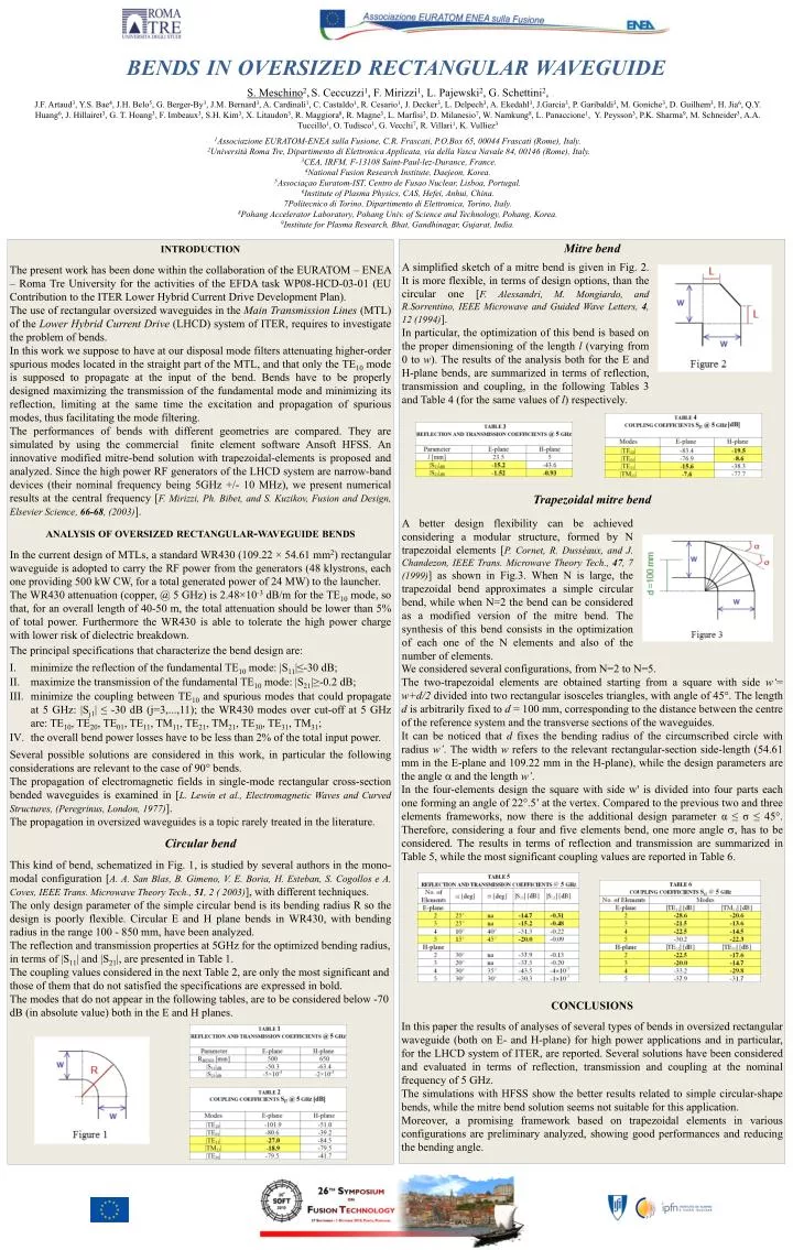
bends in oversized rectangular waveguide S. Meschino2,S. Ceccuzzi1, F. Mirizzi1, L. Pajewski2, G. Schettini2, J.F. Artaud3, Y.S. Bae4, J.H. Belo5, G. Berger-By3, J.M. Bernard3, A. Cardinali1, C. Castaldo1, R. Cesario1, J. Decker3, L. Delpech3, A. Ekedahl3, J.Garcia3, P. Garibaldi3, M. Goniche3, D. Guilhem3, H. Jia6, Q.Y. Huang6, J. Hillairet3, G. T. Hoang3, F. Imbeaux3, S.H. Kim3, X. Litaudon3, R. Maggiora8, R. Magne3, L. Marfisi3, D. Milanesio7, W. Namkung8, L. Panaccione1, Y. Peysson3, P.K. Sharma9, M. Schneider3, A.A. Tuccillo1, O. Tudisco1, G. Vecchi7, R. Villari1, K. Vulliez3 1Associazione EURATOM-ENEA sulla Fusione, C.R. Frascati, P.O.Box 65, 00044 Frascati (Rome), Italy. 2Università Roma Tre, Dipartimento di Elettronica Applicata, via della Vasca Navale 84, 00146 (Rome), Italy. 3CEA, IRFM, F-13108 Saint-Paul-lez-Durance, France. 4National Fusion Research Institute, Daejeon, Korea. 5Associaçao Euratom-IST, Centro de Fusao Nuclear, Lisboa, Portugal. 6Institute of Plasma Physics, CAS, Hefei, Anhui, China. 7Politecnico di Torino, Dipartimento di Elettronica, Torino, Italy. 8Pohang Accelerator Laboratory, Pohang Univ. of Science and Technology, Pohang, Korea. 9Institute for Plasma Research, Bhat, Gandhinagar, Gujarat, India. introduction The present work has been done within the collaboration of the EURATOM – ENEA – Roma Tre University for the activities of the EFDA task WP08-HCD-03-01 (EU Contribution to the ITER Lower Hybrid Current Drive Development Plan). The use of rectangular oversized waveguides in the Main Transmission Lines (MTL) of the Lower Hybrid Current Drive (LHCD) system of ITER, requires to investigate the problem of bends. In this work we suppose to have at our disposal mode filters attenuating higher-order spurious modes located in the straight part of the MTL, and that only the TE10 mode is supposed to propagate at the input of the bend. Bends have to be properly designed maximizing the transmission of the fundamental mode and minimizing its reflection, limiting at the same time the excitation and propagation of spurious modes, thus facilitating the mode filtering. The performances of bends with different geometries are compared. They are simulated by using the commercial finite element software Ansoft HFSS. An innovative modified mitre-bend solution with trapezoidal-elements is proposed and analyzed. Since the high power RF generators of the LHCD system are narrow-band devices (their nominal frequency being 5GHz +/- 10 MHz), we present numerical results at the central frequency [F. Mirizzi, Ph. Bibet, and S. Kuzikov, Fusion and Design, Elsevier Science, 66-68, (2003)]. analysis of oversized rectangular-waveguide bends In the current design of MTLs, a standard WR430 (109.22 × 54.61 mm2) rectangular waveguide is adopted to carry the RF power from the generators (48 klystrons, each one providing 500 kW CW, for a total generated power of 24 MW) to the launcher. The WR430 attenuation (copper, @ 5 GHz) is 2.48×10⁻³ dB/m for the TE10 mode, so that, for an overall length of 40-50 m, the total attenuation should be lower than 5% of total power. Furthermore the WR430 is able to tolerate the high power charge with lower risk of dielectric breakdown. The principal specifications that characterize the bend design are: minimize the reflection of the fundamental TE10 mode: |S11|≤-30 dB; maximize the transmission of the fundamental TE10 mode: |S21|≥-0.2 dB; minimize the coupling between TE10 and spurious modes that could propagate at 5 GHz: |Sj1| ≤ -30 dB (j=3,...,11); the WR430 modes over cut-off at 5 GHz are: TE10, TE20, TE01, TE11, TM11, TE21, TM21, TE30, TE31, TM31; the overall bend power losses have to be less than 2% of the total input power. Several possible solutions are considered in this work, in particular the following considerations are relevant to the case of 90° bends. The propagation of electromagnetic fields in single-mode rectangular cross-section bended waveguides is examined in [L. Lewin et al., Electromagnetic Waves and Curved Structures, (Peregrinus, London, 1977)]. The propagation in oversized waveguides is a topic rarely treated in the literature. Circular bend This kind of bend, schematized in Fig. 1, is studied by several authors in the mono-modal configuration [A. A. San Blas, B. Gimeno, V. E. Boria, H. Esteban, S. Cogollos e A. Coves, IEEE Trans. Microwave Theory Tech., 51, 2 ( 2003)], with different techniques. The only design parameter of the simple circular bend is its bending radius R so the design is poorly flexible. Circular E and H plane bends in WR430, with bending radius in the range 100 - 850 mm, have been analyzed. The reflection and transmission properties at 5GHz for the optimized bending radius, in terms of |S11| and |S21|, are presented in Table 1. The coupling values considered in the next Table 2, are only the most significant and those of them that do not satisfied the specifications are expressed in bold. The modes that do not appear in the following tables, are to be considered below -70 dB (in absolute value) both in the E and H planes. Mitre bend Trapezoidal mitre bend We considered several configurations, from N=2 to N=5. The two-trapezoidal elements are obtained starting from a square with side w‘= w+d/2 divided into two rectangular isosceles triangles, with angle of 45°. The length d is arbitrarily fixed to d = 100 mm, corresponding to the distance between the centre of the reference system and the transverse sections of the waveguides. It can be noticed that d fixes the bending radius of the circumscribed circle with radius w’. The width w refers to the relevant rectangular-section side-length (54.61 mm in the E-plane and 109.22 mm in the H-plane), while the design parameters are the angle and the length w’. In the four-elements design the square with side w' is divided into four parts each one forming an angle of 22°.5’ at the vertex. Compared to the previous two and three elements frameworks, now there is the additional design parameter α ≤ σ ≤ 45°. Therefore, considering a four and five elements bend, one more angle , has to be considered. The results in terms of reflection and transmission are summarized in Table 5, while the most significant coupling values are reported in Table 6. CONCLUSIONS In this paper the results of analyses of several types of bends in oversized rectangular waveguide (both on E- and H-plane) for high power applications and in particular, for the LHCD system of ITER, are reported. Several solutions have been considered and evaluated in terms of reflection, transmission and coupling at the nominal frequency of 5 GHz. The simulations with HFSS show the better results related to simple circular-shape bends, while the mitre bend solution seems not suitable for this application. Moreover, a promising framework based on trapezoidal elements in various configurations are preliminary analyzed, showing good performances and reducing the bending angle. A simplified sketch of a mitre bend is given in Fig. 2. It is more flexible, in terms of design options, than the circular one [F. Alessandri, M. Mongiardo, and R.Sorrentino, IEEE Microwave and Guided Wave Letters, 4, 12 (1994)]. In particular, the optimization of this bend is based on the proper dimensioning of the length l (varying from 0 to w). The results of the analysis both for the E and H-plane bends, are summarized in terms of reflection, transmission and coupling, in the following Tables 3 and Table 4 (for the same values of l) respectively. A better design flexibility can be achieved considering a modular structure, formed by N trapezoidal elements [P. Cornet, R. Dusséaux, and J. Chandezon, IEEE Trans. Microwave Theory Tech., 47, 7 (1999)] as shown in Fig.3. When N is large, the trapezoidal bend approximates a simple circular bend, while when N=2 the bend can be considered as a modified version of the mitre bend. The synthesis of this bend consists in the optimization of each one of the N elements and also of the number of elements.