Download
1 / 37
370 likes | 502 Views
Tonga Institute of Higher Education. IT253: Computer Organization. Lecture 7: Logic and Gates: Digital Design. Logic. Logic is a branch of math that tries to look at problems in terms of being either true or false. It will use a set of statements to derive new “true” statements.

E N D
Tonga Institute of Higher Education IT253: Computer Organization Lecture 7: Logic and Gates: Digital Design
Logic • Logic is a branch of math that tries to look at problems in terms of being either true or false. • It will use a set of statements to derive new “true” statements. • Computers rely heavily on logic to run programs. • “If” and “else if” statements in programming language are a form of logic that computers use • If x is equal to 5 then do something • if (x == 5) { do something; }
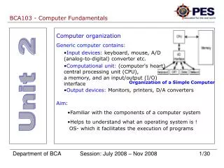
Logic in Hardware • Computers must simulate logic in hardware. To do this, it must use special pieces that can act like logic functions • Example: CPUs use transistors • Transistors are switches that are “on” or “off” • “On” means there is an electrical current • “Off” means there is no electrical current • We can use these to mean either true or false. • On = true = 1 = electricity detected • Off = false = 0 = no electricity detected
Boolean Algebra • Boolean algebra uses logic to analyze and perform operations on variables • Boolean means the math uses just true and false • Boolean “functions” can always be represented with a truth table
Boolean math • We use the symbols • * for AND • + for OR • ~ for NOT • In C++ and Java, (and most programming languages) • “&&” is used for AND • “||” is used for OR • “!” is used for NOT
Boolean Algebra • With these symbols we can now write functions, such as • F(a,b,c) = (a * b) + (~c * b * a) • If you solve this function, it means you find all the values of a, b, and c so that F(a,b,c) is true. • For example, if a = true, b = true and c = false, then F = true. • How do we find all the possible values of F? • We make a truth table
Truth Table • F(a,b,c) = (a * b) + (~c * b * a)
Truth Tables • If all the values you get for the function are true (or 1), then it is a tautology • Example: Tautology
Simplifying Boolean Equations • Let’s try to simplify this equation F1 = c*(~a*~b + ~a*b + a*~b + a*b) F1 = c*(~a*(~b+b) + a*(~b+b)) F1 = c*(~a*(1) + a*(1)) F1 = c*(~a + a) F1 = c*(1) F1 = c
Fundamental Theorem of Boolean Algebra • Every Boolean function can be changed into a special format called “sum of products.” • “Sum of products” means that the formula will look like • (a * b * ~c) + (~a*b*c) + (a*b*c) +… • The parts in parenthesis are the products (a product is the name when you multiply something) • The “+” represents the “sum” part of the “sum of products”
Fundamental Theorem What is the “sum of products” form for this formula? “Sum of products” also called The “disjunctive normal form”
Finding Equations from Truth Tables • If you have a truth table, it's easy to find a formula that represents the same values • Notice: because you can reduce, it's impossible to know the original formula. You can only find the "normal form" • Steps: • For each value that is a one, take the values of each variable and put them together in an and statement • Put all the and statements together with Ors
Finding Formulas For each line that ends in 1, take the values and AND them F(a,b,c) = 1 when ~a*~b*c ~a*b*~c a*b*c Put them together with Ors F(a,b,c) = (~a*~b*c) + (~a*b*~c) + (a*b*c)
Theory -> Reality • We should know the math theory about boolean algebra. • With that theory, we can put it to use in the real world with Boolean "gates". • Boolean gates are the simple electronic parts that simulate boolean logic. • When you put a lot of boolean gates together, you can build a CPU
Reality • A two input boolean gate is a gate that simulates a formula with only two variables. Ex. F(a,b) = (a*b) • A two input boolean gate uses between 1 and 4 transistors • A Pentium 4 CPU has 42 million transistors (so maybe 7-10 million boolean gates. • Some gates will use more transistors)
Circuits • Anything that has more than one gate connected together is called a circuit. • You can connect gates together with metal wire that can conduct electricity • A circuit represents a way for electricity (1 ands 0) (true and false) to travel through gates and perform tasks like add, subtract, etc. • By connecting the output from one gate to the input of another gate we can form very complicated circuits
Logic Gates- AND / OR in action AND Gates OR Gates 1 1 1 1 1 1 0 1 1 0 1 0 0 0 0 0 0 0
Logic Gates – More examples AND NOT 0 1 0 1 OR NOT 1 0 1 0
Addition • We have seen the common gates that are used as building blocks • We can put these gates together to make a circuit that can do things like add and subtract. • If we put the right ones together we can make a CPU. • We will look at how to implement addition with gates
Addition • Here is our truth table for addition This means we use the following formulas Sum = ( (~A*B) + (A*~B) ) = (A XOR B) Carry = (A * B) = (A AND B)
Addition We can also just use OR and AND gates to do the same As XOR and AND. In fact any circuit we make can be made in using only AND and OR gates,
Addition • What we have created is a adder circuit, but it is actually only a “half adder.” • We have made it so that it will compute the sum and the "carry-out," but there is no "carry-in." • To make a “full-adder” we need to account for the "carry-in" This is the Half adder picture we will use in the future. We know this picture represents the boolean gates that make a half-adder. We just draw a simple box instead
Addition • To make a full-adder is a little more complicated. • Here's the truth table
Full -Adder • We can create a full adder by putting two ½ adders together with some extra gates to connect the "carry-in" Now we can represent this whole circuit As this one “full adder box” -
Did we just make a CPU? • What we made was a circuit with boolean gates (each gate made up of 1-4 transistors), that can add two bits together. • Example 1 +0 1 • Since computers need to add numbers together that are bigger than 1, we need to put more full adders together
A ripple adder • Let’s pretend our computer uses 4 bit numbers (ex. 1011). • Most computers today use 32 bits • We can put four full adders together to add the 4 bits • This is a “ripple adder” because each addition requires the carry in from the previous. • You can’t add a3 + b3 without doing all the other ones before • This is very slow • There are faster ways
Another Circuit - MUX • MUX – Multiplexor – This circuit will select an input. • If there are two possible inputs to use for something, and you want to select one of them, you can use a MUX to select for you.
Multiplexors • The first one we looked at is a 2x1 MUX, meaning it has 2 inputs, and 1 selector. • It is simple to create larger MUXs if we have more inputs like a 4x1 MUX
Summary • Logic • Boolean algebra (functions, truth tables, simplification, fundamental theorem, deMorgan’s Laws) • Circuits and Logic Gates (boolean gates) • Addition in gates (1/2 adder, full adder, ripple adder) • MUXs