Download
1 / 21
210 likes | 318 Views
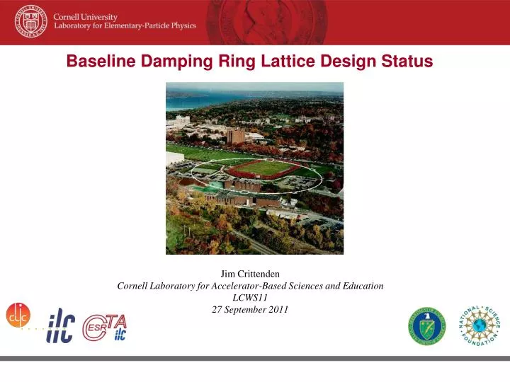
Jim Crittenden Cornell Laboratory for Accelerator-Based Sciences and Education LCWS11 27 September 2011. Baseline Damping Ring Lattice Design Status. DTC02 Layout (D.L.Rubin). Circumference = 3238.681 m Harmonic number =7022 710-m straights ~ 6 phase trombone cells

E N D
Jim Crittenden Cornell Laboratory for Accelerator-Based Sciences and Education LCWS11 27 September 2011 Baseline Damping Ring Lattice Design Status
DTC02 Layout(D.L.Rubin) Circumference = 3238.681 m Harmonic number =7022 710-m straights ~ 6 phase trombone cells Sixty 2.1-m long wigglers: 30-cm period, 14 poles Bmax = 2.16T Space for 16 RF cavities The cryostats for upper and lower positron rings are interleaved.
Arc Cell - FDBDF Cell length = 10.93m Bend length = 3.0m 75 cells/arc
DTC02 Lattice Functions Arc Arc Inj-Ext Straight Wig-RF Straight
Wiggler Cells Wiggler parameters 14 poles 30-cm period Wiggler length = 2.1m Cell length = 7.56 m 30 wiggler cells 2 wiggler cells
RF Cavities The lattice can accommodate 16 RF cavities If we assume 12 cavities then: Voltage/cavity in 10 Hz mode is 1.64 MV Power/coupler in 5 Hz, high power mode is 300 kW
Dynamic Aperture 5 Hz Periodic type wiggler model, includes vertical focusing and cubic nonlinearity
Dynamic Aperture 10 Hz Periodic type wiggler model, includes vertical focusing and cubic nonlinearity
Global Design Effort Magnet Count (Damping Ring)
Damping Wiggler Redesign CESR-c Damping Ring Studies in the Context of the ILC Damping Ring Wigglers PAC 2005 J.Urban and G.Dugan Design Considerations and Modeling Results for ILC Damping Ring Wigglers Based on the CESR-c Superconducting Wiggler PAC 2007 M.A.Palmer, J.A.Crittenden and J.Urban Period reduced from 32 to 30 cm and number of poles increased from 12 to 14. Gap reduced from 8.64 cm to 7.62 cm. Peak field increased from 2.0 to 2.16 T.
Wiggler Field Analytic Form for Symplectic Tracking A Magnetic Field Model for Wigglers and Undulators, , PAC 2003, D. Sagan, J.A. Crittenden, D.L. Rubin and E. Forest The field map has been posted on the ILC/CesrTA wiki. A conceptual design for costing purposes is in preparation. 1200-term optimization underway. Residuals presently at the level of a few gauss. The parameters have been posted on the wiki.
Work at Cornell directed towards: Implementation of mitigation recommendations into the vacuum chambers Need chamber profiles for next round of physics simulations Need chamber and system conceptual design for costing Vacuum System Design Effort
Wiggler Chamber Concept I NEG strips Clearing Electrode E-beam weld locations Copper Chamber
We are considering a scenario where 2 wigglers with a quad in center are assembled as a unit and then installed. This would reduce the number of electrode chambers required. Wiggler Chamber Concept II
Aluminum Dipole Chamber Concept Radial inside of ring Radial outside of ring Locations of NEG strips
Tasks underway Concepts for drift, quadrupole, sextupole chambers in arcs Pumping requirements for straights Will in-situ bakeout of chambers in the straights be required? What are our options? Full ring wall profile for EC simulations Tasks to do Photon stop & masks conceptual design in wiggler region Full system concept for costing Vacuum System Summary