Download
1 / 21
210 likes | 347 Views
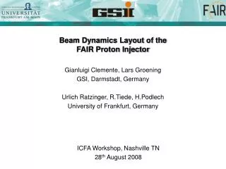
The FAIR Proton Linac. Outline Requirements to Proton Linac Source, RFQ, DTL, RF Beam Dynamics Civil Construction. FAIR: F acility for A ntiproton and I on R esearch. 7 10 10 cooled pbar / hour. 100 m. Accelerator Chain for Cooled Antiprotons. <=100 x : 4 x :

E N D
The FAIR Proton Linac • Outline • Requirements to Proton Linac • Source, RFQ, DTL, RF • Beam Dynamics • Civil Construction
FAIR: Facility for Antiproton and Ion Research 71010 cooled pbar / hour 100 m
Accelerator Chain for Cooled Antiprotons <=100 x : 4 x : Injection of protons into SIS18 Acceleration to 2 GeV Injection into SIS100 Acceleration to 29 GeV Impact on target hot pbars Stoch. pbar cooling in CR Injection into in RESR Injection into HESR Acceleration to 14.5 GeV or Deceleration in NESR to 30 MeV Extraction to low energy pbar experiments
Injection into Synchrotron SIS18 • The client of the p-linac is SIS18 • Number of protons that can be put into SIS18 limited to • , i.e. depends on energy • Number of SIS18 turns during injection depends on phase space areas acceptance of SIS18 ηMTI := green area / red area = filling factor p-linac SIS18 single shot from p-linac ( emittance ~ size2 ~ γ-1 ) • Injection energy → duration → current → emittance ε are coupled • ηMTI → 60% (good empiric value) Energy remains to be chosen
final rate of cooled pbar depends on injector energy: 70 MeV → 16.5 mA / µm → Choice of Proton Linac Energy limited by stoch. cooling power • I = 35 mA • βγεx = 2.1 µm
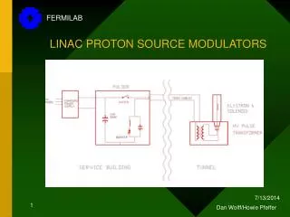
p-Linac Overview Diagnostic insertion • ECR proton source & LEBT • RFQ • 2 re-bunchers • 2*6 accelerating cavities • 5 MW of beam loading (peak), 710 W (average) • 11 MW of total rf-power (peak), 1600 W (average) • 2 dipoles, 45 quadrupoles, 7 steerers • 10 turbo pumps, 34 ion pumps, 9 sector valves • 41 beam diagnostic devices
Partners and People • University of Frankfurt • Cavity design • RFQ design (4-rod) • Beam dynamics • CEA/Saclay • Proton source & LEBT • ITEP Moscow • RFQ design (4-vane) • GSI Darmstadt • Cavity design, Beam dyanamics/diagnostics, Magnets, • Power converters, Rf-sources, Proton source, • Diagnostics, UHV, Civil constr., Controls, Coordination U.Ratzinger, A.Schempp, R.Tiede R.Gobin et al. S.Mineav et al. G.Aberin-Wolters, R.Bär, W.Barth, G.Clemente, P.Forck, L.Groening, R.Hollinger, C.Mühle, H.Ramakers, H.Reich, W.Vinzenz, S.Yaramyshev
Proton Source & LEBT 95 keV Requirements at LEBT exit: SILHI at CEA/Saclay: 95 keV, > 100 mA, dc
Beam Measurements at CEA/Saclay LEBT exit: two measurements using different electronics, separated by 4 days, intermediate opening of the plasma chamber: optics for RFQ-injection • During 3 weeks of measurements : • always reliable & stable 100 mA beam • no single sparking of the HV • no interruption due to any malfunction • Measured beam parameters meet ..the requirements to FAIR p-linac • Stable source needed for production ..machine like p-linac
Radio Frequency Quadrupole (RFQ) 3.5 m 3.0 MeV 0.1 MeV Two designs followed: 4-rod (cheaper) 4-vane (state of the art) Both designs meet requirements
Drift Tube Linac DTL 3.0 MeV 70 MeV • DTL: wall plug power → em. (rf) fields (325 MHz) → proton beam power • Creation of rf-power is project cost driver • 64% of p-linac project cost related to rf-power
Rf-Power Source (Klystron) • klystron: wall plug power → rf-field power • industrial devices • length ≈ 5 m • weight ≈ 2.5 tons • TOSHIBA Klystron 3740A/GSI • peak rf-power 3.0 MW • no R&D related cost & risks • first device ordered • delivery in March 2008
Accelerating Cavities rf-power → beam power rf → beam power conversion efficiency CH conventional • Crossed-bar H-Cavity (CH) • New development for FAIR p-linac
Accelerating Cavities 3.0 MeV 70 MeV • Rf-coupling of CH-cavities: • reduce number of klystrons • reduce place requirements • profit from 3 MW klystron development • avoid rf-power line splitting • reduce cost for rf-equipment E – Field rf-coupling cell H – Field 1:2 Model
Rf-Power Requirements DTL Beam RFQ Buncher Buncher Heat per rf-load (incl. margin): • 7 Klystrons • 2 solid state amplifiers, IOTs, ... • 1 power converter / rf-source
R&D: Testing of Klystron & CH-Cavity Operation • Choice of Toshiba klystron & CH-cavities approved by ext. committees • But: • CH-cavities never built • 3 MW klystrons never operated at GSI • Rf-test stand mandatory for testing and staff training klystron (protection) cavity radiation shielding power supplies
Beam Dynamics Layout proton beam envelopes → full transmission x / y [mm] final phase space distributions still too high by 35% OK OK
Beam Dynamics, Losses due to Machine Errors, Hot Spots magnet alignment accelerating field voltage accelerating field phase
Civil Construction • 1800 m2 of space required; 7700 m3 • 1200 kW of peak power consumption • 450 kW of water cooling • 200 kW of air cooling Ground floor Second floor
Steps in near Future • Construction of prototype CH-cavity just started; ends Q3/2009 • Rf-test stand construction will start in 2008; ends Q1/2009 • CH-cavity testing in 2009 / 2010