Download
1 / 41
560 likes | 1.12k Views
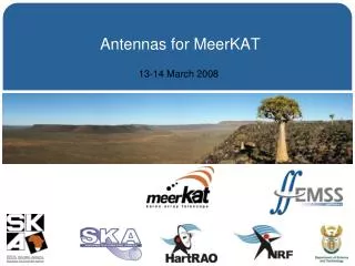
MeerKAT Radio Telescope. Willem Esterhuyse MeerKAT Project Manager willem@ska.ac.za 083 447 1615. Introduction. Presenting work from BAE/MMS/EMSS/SE etc . In many cases preliminary results Very Short /KAT7 MeerKAT overview Phases (XDM/KAT7/MeerKAT), composite dishes, progress

E N D
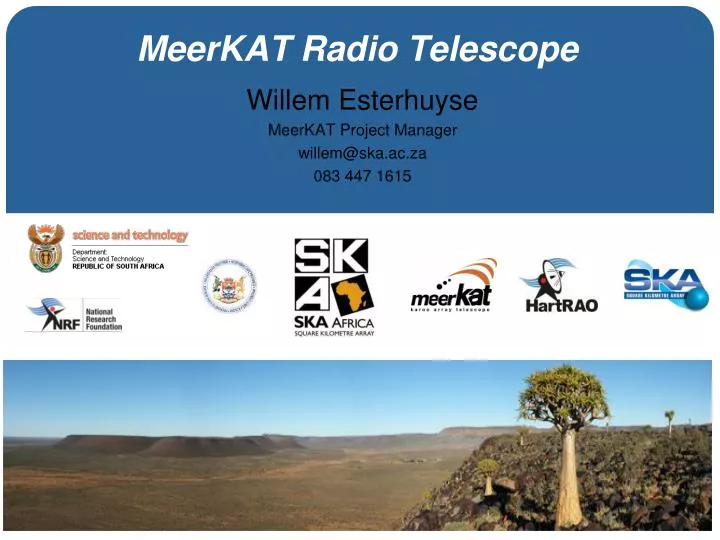
MeerKAT Radio Telescope Willem Esterhuyse MeerKAT Project Manager willem@ska.ac.za 083 447 1615
Introduction • Presenting work from BAE/MMS/EMSS/SE etc. • In many cases preliminary results • Very Short /KAT7 MeerKAT overview • Phases (XDM/KAT7/MeerKAT), composite dishes, progress • Antenna on critical path - rest of this talk • CoDR to MeerKAT Antenna Spec • Open Issues from CoDR addressed • Additional work required - from concept to reality • Spec changes to arrive at final system spec • Schedule/Infrastructure Interfaces (infrastructure accelerated) • Had to fix interfaces early • Other Antenna risks (not addressed above) • KAT7 – MeerKAT: Impact on Infrastructure
Antenna Manufacture (KAT7) Off-site On-site
Reflector Manufacture (KAT7) Mould Setup Lay-up/ Transfer Mould Segments Assemble Pattern Process qualified – last 4 KAT7 dishes production quality Machine Pattern Segments
MeerKAT Overview (1) KAT7 MeerKAT • Dec 2007: XDM set to work • ********************************************************** • Jan 2008: Project start (+XDM learning) • April 2008: Antenna contract awarded • Aug 2008: Antenna CDR • Feb 2009: Mould setup on site • Feb 2009: Receiver CDR • Feb 2009: Software approach revisited • Feb 2009: RFE contracts awarded • May 2009: First antenna installed on site • Dec 2009: 5 dishes, 2 receivers, FF correlator • Dec 2009: Fringes • April 2010: 7 dishes, 4 receivers • April 2010: First Image • July 2010: SKA RFI campaign • Oct 2010: ESKOM power on site • Oct 2010: Cold receiver installation • Nov 2010: 10 Mbps link to CT • Dec 2010: 3 cold receivers, 16 element correlator • Jan 2011: Remote observation demonstration • May 2011: UPS installation • July 2011: 7 Cold Feeds • Dec 2011: Engineering completion • March 2010: Science Proposals • July 2010: CoDR • Sept 2010: MeerKAT scope change • Oct 2010: TAC • Jan 2011: URS finalized • Jan 2011: System Spec finalized • July 2011: System PDR • Dec 2011: Antenna Tender • Mar/April 2012: Antenna Contract Award current
MeerKAT Overview (2) • March 2010: Science Proposals received. • July 2010: CoDR (options for MeerKAT with performance, budget, schedule implications on system level for all options presented to and reviewed by international panel who are experts in their fields. • Resulted in change to 64 x 13.5m offset antennas recommendation to steering committee. • Sept 2010: Change (schedule, budget) approved by steering committee. • Oct 2010: TAC input to finalize URS (evaluation of science proposals) • Accepted science proposals drive User Requirement • Jan 2011: System Spec version 1, URS version 2 • Mar 2011: Operational URS • July 2011: System PDR successfully completed • Followed by sub-system “thin specs”, detail spec development • Dec 2011: Antenna Tender (need a spec) • March/April 2012: Antenna Contract award – very tight
MeerKAT – PDR (Panel comments) • “The panel unanimously concludes that the PDR has been successfully passed and congratulates the project teams.” • “Clear and thorough set of documents, made available to the panel well in time.” • “We are extremely impressed by the quality of the project team, and the continued tremendous progress in realising KAT-7 and bringing MeerKAT to its current stage.” • “We commend the project for their intelligent approach towards systems engineering, looking after the fundamental technology development as well as implementing formal procedures.” • “The project has a good baseline of science requirements with a strong and complete analysis leading to system requirements.” • “There has been good interaction with the science community so far.” • “We conclude that the baseline system design satisfies the system requirements.” • CAM: “We’re impressed by the well-engineered system, the extended simulation program and the way in which KAT-7 is used for staged development.”
MeerKAT Overview - Antenna 0.95/0.32mm 1 2 3
CoDR to MeerKAT Antenna Composite reflector Counter-weights Sub Reflector Steel Yoke Steel Pedestal Connecting Structure Feed Indexer
CoDR to MeerKAT Antenna (1) • Open Issues from CoDR addressed • Carbon Fibre cost effect • Alignment of reflectors/Surface Accuracy • Curing Distortions (reflector not symmetric) • FEA to predict curing distortions • Construct 1.8m offset dish • Survey mould/dish to determine distortion • Compare to FEA and update FEA if required • Implement on MeerKAT FEA (main and sub-reflector) • Connecting Beam stiffness • Tolerances/Alignment of sub-reflectors and receiver • Composite Material Qualification for use on Radio Telescopes
Reflector Manufacture (KAT7) Mould Setup Lay-up/ Transfer Mould Segments Assemble Pattern Process qualified – last 4 KAT7 dishes production quality Machine Pattern Segments
Eliminate 1 and 2 Current solution good enough for MeerKAT Study to improve major error contributors (4 and 6) underway MeerKAT Mould Design/Surface Accuracy
OG – Surface Accuracy Calc • Algorithm developed jointly by BAE, EMSS • Verified • Impacted by change in requirements (see later)
Curing Distortions • 5 offset dishes (1.8m diameter moulded) – different resins • 2 x polyesters, 1 x vinyl-ester en 2 x epoxy resins • Same conditions as foreseen for MeerKAT manufacturing • Mould and dishes measured • Difference plotted as distortions • Temperature effects • Chemical (resin shrinkage) • Study not completed
Connecting Beam Stiffness • CoDR – 1.5 to 1.8 Hz • After further structural/EM optimization – risk retired • 1st mode 3+ Hz (“yes” mode) • 2nd mode (sideways) more than 4 Hz (“no” mode) • Coupling to wind (non-issue if around 2 Hz) • Control (preferably 3 Hz or higher) • Displacement of subreflector and receiver and subsequent effect on pointing discussed later
Material Qualification • Material qualification • Structural (reflective surface) • Environmental (UV/corrosion/fungus) • Radio quality evaluation of reference and tested panels • Structural tests almost completed • Strength, stiffness, shear properties • Fatigue • Creep • Environmental tests in progress • Test program scheduled for completion Dec 2011
Material Qualification • Thermal Fatigue
Material Qualification • Thermal Mechanical Fatigue Test No of cycles = 365x30x5, “Run-out” 1e6 cycles
Material Qualification • Thermal Mechanical Fatigue Test Manufacturing void (microscopic) – no evidence of deterioration in thermal fatigue run-out test
Material Qualification • Mechanical properties (ASTM/ISO) • Tension • Compression • Shear • Creep
CoDR to MeerKAT Antenna (2) • Additional work required - from concept to reality • Finalize Optical Layout • MMS/EMSS interaction • Receiver (Concept layout done) • Spec changes to final system spec (focus major ones) • Availability/Reliability and implications on system spec • Surface accuracy • Pointing accuracy • System Spec • Achieve spec day 1, but keep upgrades in mind • Later improvements planned • Operational conditions (mainly impact of wind) • Wind load investigation • CFD (qualified)
MeerKAT Dish Optics • Preliminary MeerKAT 13.5m optics (optimised for 64 dishes) • FEA/EM study running in parallel to finalize optimized EM solution that is structurally feasible
Availability (impact on wind specs) • Can loose 8% of time due to wind – worked on 94% wind availability (i.e. 2% safety factor)
Pointing • Optimal Conditions: 5” (max 15” jitter), with reference pointing • Normal Conditions: 25” • Temperature sensors fitted, not implemented in pointing – future
Pointing Summary 5” • Reference Pointing required (otherwsie to expensive) • * (Ambient Temperature compensation OFF)
Pointing Summary 25” • More work required • Thermal sensors implemented for improvements later
MeerKAT Studies - CFD • Obtain Cp: • Completed in Dec 2012 • Verify approach by running analyses with same assumptions on known analytical solution and compare results
Schedule/Infrastructure Interfaces • Mould/Trolley design (make sure fit in shed/schedule) • Consider options of machining entire mould (too expensive) • Integrate cooling • Done Jan 2012
Risks not addressed • Composite reflector • Experience on XDM and KAT7 • Durability of composites (includes reflectivity) • Reflector accuracy (curing distortions) • Operational performance • Wind loading • Pointing • (Thermal modelling) • Ball-screw • Single-point failure (duty cycle/safety) • Elevation Stage • Drive (sizing/power consumption) • Bearing • Cable Wrap • Encoder Mount Reliability Lightning Protection • Sub Reflector • Accuracy • Feed Indexer • Durability • Cable Wrap • Azimuth Stage • Drive • Bearing • Cable Wrap • Encoder Mount • Connecting Beam • Stiffness (control/ subreflector + feed support • ACU • Functionality • Reliability/Robustness • Control system influence pointing • Foundation • Stability
Impact on Infrastructure • Impact on Infrastructure • Dish Shed Extension • Foundations • Bigger reflector (wind) • Tighter pointing spec • Feed low OG – higher forces in wind stow • Pedestal Integration Area
Foundations: Stow important • Stow • 90 deg elevation • No water accumulation – robust and safe • No compromise on reflector/radio surface • Cost impact on structure is small • Foundations • 5” RMS allowed for movement due to wind under operational conditions • Piling (different lenghts) with CAP best option for all soil types encountered on MeerKAT site
Site Complex Upgrade
Conclusion • OG does represent challenges • Work in the last year achieved the following • Optics definition (shaping?) • Specification development (significant impact on solution – wind) • Includes work to show there is a solution • Verification written along with spec • Composite material qualification (Dec 2011) • Includes curing distortions (Dec 2011) • Reflector alignment/Surface accuracy – algorithm developed and verified – used in concept analyses (verify pointing/accuracies) • CFD – results used in concept analyses FEA • Retired risk on connecting beam stiffness • Interfaces to Infrastructure (foundation lacks final detail, loading specified) • RFI process (verify schedule, budget, technical performance from suppliers) – no serious concerns