Download
1 / 22
270 likes | 869 Views
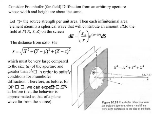
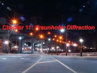
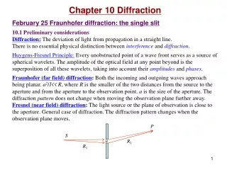
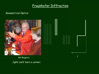
Fraunhofer Diffraction: Circular aperture. Wed. Nov. 27, 2002. Fraunhofer diffraction from a circular aperture. . y. . P. r. x. . Lens plane. Fraunhofer diffraction from a circular aperture. Path length is the same for all rays = r o. Do x first – looking down. Why?. .

E N D
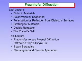
Fraunhofer Diffraction: Circular aperture Wed. Nov. 27, 2002
Fraunhofer diffraction from a circular aperture y P r x Lens plane
Fraunhofer diffraction from a circular aperture Path length is the same for all rays = ro Do x first – looking down Why?
Fraunhofer diffraction from a circular aperture Do integration along y – looking from the side P +R y=0 ro -R r = ro - ysin
Fraunhofer diffraction from a circular aperture The integral where J1() is the first order Bessell function of the first kind.
Fraunhofer diffraction from a circular aperture • These Bessell functions can be represented as polynomials: • and in particular (for p = 1),
Fraunhofer diffraction from a circular aperture • Thus, • where = kRsin and Io is the intensity when =0
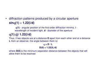
Fraunhofer diffraction from a circular aperture • Now the zeros of J1() occur at, • = 0, 3.832, 7.016, 10.173, … • = 0, 1.22, 2.23, 3.24, … • =kR sin = (2/) sin • Thus zero at sin = 1.22/D, 2.23 /D, 3.24 /D, …
Fraunhofer diffraction from a circular aperture The central Airy disc contains 85% of the light
Fraunhofer diffraction from a circular aperture D sin = 1.22/D
Diffraction limited focussing • sin = 1.22/D • The width of the Airy disc W = 2fsin 2f = 2f(1.22/D) = 2.4 f/D W = 2.4(f#) > f# > 1 • Cannot focus any wave to spot with dimensions < f D
Fraunhofer diffraction and spatial resolution • Suppose two point sources or objects are far away (e.g. two stars) • Imaged with some optical system • Two Airy patterns • If S1, S2 are too close together the Airy patterns will overlap and become indistinguishable S1 S2
Fraunhofer diffraction and spatial resolution • Assume S1, S2 can just be resolved when maximum of one pattern just falls on minimum (first) of the other • Then the angular separation at lens, • e.g. telescope D = 10 cm = 500 X 10-7 cm • e.g. eye D ~ 1mm min = 5 X 10⁻⁴ rad
Matrix treatment of polarization • Consider a light ray with an instantaneous E-vector as shown y Ey x Ex
Matrix treatment of polarization • Combining the components • The terms in brackets represents the complex amplitude of the plane wave
Jones Vectors • The state of polarization of light is determined by • the relative amplitudes (Eox, Eoy) and, • the relative phases ( = y - x) of these components • The complex amplitude is written as a two-element matrix, the Jones vector
y x Jones vector: Horizontally polarized light The arrows indicate the sense of movement as the beam approaches you • The electric field oscillations are only along the x-axis • The Jones vector is then written, where we have set the phase x = 0, for convenience The normalized form is
y x Jones vector: Vertically polarized light • The electric field oscillations are only along the y-axis • The Jones vector is then written, • Where we have set the phase y = 0, for convenience The normalized form is
y x Jones vector: Linearly polarized light at an arbitrary angle • If the phases are such that = m for m = 0, 1, 2, 3, … • Then we must have, and the Jones vector is simply a line inclined at an angle = tan-1(Eoy/Eox) since we can write The normalized form is
Jones vector and polarization • In general, the Jones vector for the arbitrary case is an ellipse y Eoy b a x Eox