Download
1 / 44
440 likes | 551 Views
RF Upgrades & Experience At JLab. Rick Nelson. Outline. Background: CEBAF / Jefferson Lab History, upgrade requirements & decisions Progress & problems along the way Present status Future directions & concerns. CEBAF at Jefferson Lab. Design 4 GeV, 200 uA 3 Experimental Halls

E N D
RF Upgrades & Experience At JLab Rick Nelson
Outline Background: CEBAF / Jefferson Lab History, upgrade requirements & decisions Progress & problems along the way Present status Future directions & concerns
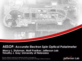
CEBAF at Jefferson Lab • Design • 4 GeV, 200 uA • 3 Experimental Halls • Present (pre-upgrade) • 6 GeV, 200 uA • 3 Experimental Halls • Upgrade • 11 GeV, 200 uA • 3 Experimental Halls • 12 GeV, 200 uA • 4th Hall D only
Upgrade magnets and power supplies CHL-2 Upgrade Existing Halls From 6 to 12 GeV
RF + Upgrades • Original • 42.5 cryomodules/338 SC cavities • 340 klystrons: 5 to 6.5 kW CW, 1497 MHz • Incremental upgrades to C50 ongoing • C25, C50 cryomodules • Upgrade • 10 cryomodules, 80 SC cavities • 80 klystrons: 13 kW CW, 1497 MHz • New designs for klystrons, power supplies, circulators, controls
Key RF Requirements 10 new zones of RF power for new accelerating structures: • 1497 MHz • Operating Gradients Required • >17.5 MV/m • RF Power per cavity • 13 kW saturated • Regulation requirements • (table) • Cavity QL • ≥ 2x10⁷ Cavity de-tuning curve
How Many RF Sources? 1 per cavity (existing configuration) Minimum impact of failures 1 per zone or 1 per linac Larger impact on faults High power splitters High power amplitude and phase control required with high precision. Additional controls and high power modulators found to be more $$ than individual RF sources. Single LINAC upgrade shown
HV DC Power Supply • Design adapted from electrostatic precipitator application (higher volts/lower amps & in oil) 1000+ units in the field at award • Highly tolerant to load faults • Lower stored energy than T-R, fast turn off on fault, series resistor limits output current (no crowbar) • Each system powers 8 klystrons (as before) • Resonant mode switcher design (15-20 KHz) • 4 separate supplies. Each feeds 2 klystrons • Minimizes klystrons taken offline due to power supply failure • Controlled as a “unit” • Each adjustable to -15kV • 15 A total
Additional Views • HV Deck (4 per system, on rollers) Rear View
Typical RF Installation All zones installed and commissioned with beam
Tunnel Connections Waveguide installation
Good Times / Bad Times • Everything according to plan? • Delivery delays on several key components • Klystron & general WG close to schedule with no problems • HOM filters, isolators, solenoid power • Revisions and rework for problem areas • One contract cancellation • Multiple installation delays with starts & stops • Largely from budget constraints • Resulting in reassignment of workforce • Inefficient to change tasks to often
Isolator Requirements • 13 kW CW, full reflection • 0.2 dB insertion loss • 21 dB isolation (any phase & power) • Water cooled • PM only - no TCU • Operates adjacent to others • Awarded to Ferrite (also supplied 350+ units for original CEBAF) • Full power testing at JLab • Vendor test capabilities missing • Several rounds of testing with sliding short • Using FA klystron at L-3 • At JLab using 2 x 6.5 kW and 13 kW klystron
Events • Initial tests looked OK and first lots were installed • Tests into WG shorts not as good • Results not repeatable/consistent with similar test connditons • And, performance varied based on phasing (Distance to short) • Two rounds of measurements & adjustments to understand the fix • Tried to characterize performance and make adjustments before next production batch • Next production units still variable
Sensitive to Match & Phase • Isolation affected by • Ferrite temperature • Magnetic field strength • Could be adjusted to maintain good performance • Less field needed at higher temperature • Other solutions include TCU, active field control (VSWR) • “Automatically” handled in small units • Reflected phase • Match (all ports) • 2 of 3 need to be good for high isolation • Load OK, short bad, klystron needs to be good (but not easily measured)
Temperature • Initial measurements done steady-state • Find position for lowest isolation (worst case, run plots) • Changes then observed at turn-on • Concerns for off-resonance conditions at turn-on • Must avoid tripping on high reflected power at turn-on • Must work under varying conditions due to differing distances to cavities
Isolation vs. Heating/Time • RF heating of ferrite resulted in significant changes over (short) time
Resolution • Vendor reworked dome – new domes, improved cooling, full rebuild all units • … results were still variable • LL tuning abandoned in favor of full power setup at JLab • 100% re-tested at power • Some adjustment to requirements allowed – lower isolation at lower power • Reflected power well below threshold for klystron damage or performance degradation • Final solution meets operational needs including credible fault conditions • All 84 units modified, tested, reinstalled • Considerable extra work -- all units were handle multiple times installed/removed/reinstalled.
HOM Filters • Uncertainty of need, though requirements known • Originally not needed, later added back in • Belief was only 2 of 8 cavities would require HOM filter • Normal procurement process • 2 vendor offers • Final units essentially identical to what we had from multiple purchases • Performance met, cost lower though alternate proposal was more robust • Small tweaks to reduce fundamental absorption • Manufacturing relied on external shops (as before) • Vendor a small concern, limited resources & staff • Fabrication subcontracted (metal fab, Iridite, dip brazing) • Dummy spool pieces installed in other positions • Had expected this to come in last
Klystron HV PS • Performance has been good overall • Switcher design and controls work well - good reliability • DSP-based controls with hardware safety interlocks • Code changes needed to address timing issues • 1 unit tested OK, but all 4 might trip external breaker • Extended step-start to deal with high inrush & breaker trips • Possible race condition for contactor control vs. status reporting (several contactors changed but seem to be OK) • Control transformers (480:120) shorted out • Loose connections/loosening connections • Contactors, IGBT • Suggestion: check connections… • No similar problems with old supplies, but a lot less connections • DC power guys regularly check transistor connections • New doesn’t mean perfect -- especially after x-country trips • A couple noticeable events
IGBT Connection Another loose connection IGBT overheating & short circuit Checked torque on all connections, all systems No early signs noted – just tripped
Problem Procurements • Isolator (discussed) • HOM filter (discussed) • Klystron solenoid PS • Offer looked good on paper • Major design effort resulted in delays and cancellation • FA looked like a lab prototype – and didn’t work long • Test results failed to meet their results (tried 3 ways) • Ultimately cancelled and purchased from Sorensen
We Didn’t Buy This One • Liberal use of RTV to insure components didn’t shift during shipping… • Kluge board • Not First Article class • Order cancelled
Installation Challenges Funding shortages resulted in work reassignments & delays Techs reassigned to dismantle other systems(multi-month delays) Start/stop/start not efficient and required relearning (In spite of this RF finished on time and below budget)
A Wet Year • Brazing issues and water leaks • Multiple new components, nuisance problems • Both believed to be of similar origin – but different suppliers • Pressure tested (but not long enough) • Trapped flux dissolved out resulted in small leaks on a few pieces • Circulator load assemblies • New loads built, and testing refined • Solenoid leaks on plumbing • Longer pressure testing with hot water
Ongoing Circulator (old style) • Reliable for a lot of years, but load failures becoming more frequent • LC DI water • 15 years+ erosion and leaching • Self-rebuilding w/o retuning • Same load back to its circulator • New circulator loads won’t experience this failure mode
Water Flows Downhill Water level – horizontal run Bleed hole was for air… All LCW was turned off during extended down (~1 year) Circulator load seals lost their seal Water in select waveguides (not our selection) HOM filters soaked
Maintenance Issues • New systems to be learned and maintained • New systems to be re-checked • Old systems getting older • Spares needed for new (and old alike) • Major PM efforts planned for summer • Pushed off many times already
Summary • All new LINAC RF has been installed and commissioned, though not without issues along the way • Operating requirements met • Staff still learning operational maintenance differences from old systems • Maintenance activities scheduled for summer down – old and new systems • Lobby to purchase spares with new equipment
12 GeV Timeline 2009 12GeV Upgrade construction starts in May with ground breaking ceremony at the Hall-D site. 2011 First C100 installed in the 2L23 slot in CEBAF, July. 2012 C100 module successfully operated at design specifications: 108MeV of energy gain with 465μ A of beam loading on May-18. 2013 North and South Linac 2K LHe operations established, Dec-09 for the first time with two CHL's plants connected to a "split CEBAF". 2013 12GeV CEBAF Beam Commissioning begins Dec-13. 2014 Beam successfully transported to the 2R dumplette with 2.2GeV/pass energy gain on Feb-05. Establishing RF capability to support 12GeV 5.5pass operation with greater than 50% availability. 2014 Injector achieves 12GeV design energy of 123MeV on Mar-10 2014 3-pass beam established to Hall-A Mar-20. Multi-pass capability established in the 12GeV era. 2014 3-pass beam with E>6GeV established to Hall-A on Apr-01 and beam-target interactions recorded. First time beam transported to an end-station with energy that exceeds maximum energy set during the 6GeV CEBAF era. 2014 10.5GeV 5.5 pass beam established to Hall-D Tagger dump on May-07. 2014 First RF separated beams in 12GeV era on Oct-??. Establishes multi-beam capability in the 12GeV era.