Download
1 / 8
80 likes | 202 Views
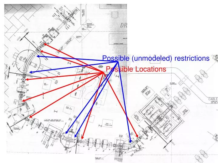
Possible (unmodeled) restrictions. Possible Locations. Possible Checks. 0th order: open up and look 1st order: Point-parallel-point optics to image shadows More wobbler studies to measure (a,b) acceptance Scattering from thick foil to measure (a,b,d) acceptance. Possible Locations.

E N D
Possible (unmodeled) restrictions Possible Locations
Possible Checks • 0th order: open up and look • 1st order: • Point-parallel-point optics to image shadows • More wobbler studies to measure (a,b) acceptance • Scattering from thick foil to measure (a,b,d) acceptance
Possible Locations • Just before Q9 (maximum y envelope) • Any of the BCMs after mass slits • Interceptor position • Other ideas?
Detector schemes • Solar cell arrays • Pros: sensitive, cheap • Cons: energy, position resolution poor, • DSSSD • Pros: E,x,y position resolution OK • Cons: expensive, sensitive • Scintillating fibers • Pros: sensitive, good position resolution • Cons: complex
(x,y)=0 • (a,b)=±20mrad • dE=±4% • SLITC=25mm • SLITC=15,25mm • SLITF=45mm Substantial loss at charge slits, but none beyond that
(x,y)=0 • (a,b)=±20mrad • dE=±4% • SLITC=45mm • SLITC=45mm • SLITF=45mm No more loss at charge slits… …but additional loss points crop up
(x,y)=0 • (a,b)=±20mrad • dE=±4% • SLITC=45mm • SLITC=45mm • SLITF=45mm ED1 field clamp limits rays
(x,y)=0 • (a,b)=±20mrad • dE=±4% • SLITC=45mm • SLITC=45mm • SLITF=45mm Even if they make it past ED1, ED2 field clamp limits rays