Download
1 / 60
650 likes | 1.1k Views
Lecture 11 Wind Power, Wind Machines. Nikola Tesla: Inventor of Induction Motor (and many other things).

E N D
Lecture 11 Wind Power, Wind Machines
Nikola Tesla: Inventor of Induction Motor (and many other things) • Nikola Tesla (1856 to 1943) is one of the key inventors associated with the development of today’s three phase ac system. His contributions include the induction motor and polyphase ac systems. • Unit of flux density is named after him Tesla statue at Niagara Falls • Tesla conceived of the inductionmotor while walking through a park in Budapest in 1882. • He emigrated to the US in 1884
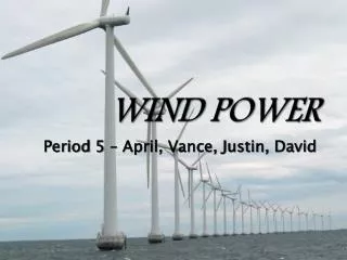
In the News: World’s Largest Offshore Wind Farm Opens Turbinesare locatedin waterdepth of 20-25m.Rowsare 800mapart; 500mbetweenturbines • “Thanet” located off British coast in English Channel • 100 Vestas V90 turbines, 300 MW capacity http://edition.cnn.com/2010/WORLD/europe/09/23/uk.largest.wind.farm/?hpt=Sbin http://www.vattenfall.co.uk/en/thanet-offshore-wind-farm.htm
Off-shore Wind • Offshore wind turbines currently need to be in relatively shallow water, so maximum distance from shore depends on the seabed • Capacityfactors tendto increaseas turbinesmove furtheroff-shore Image Source: National Renewable Energy Laboratory
Maximum Rotor Efficiency Constraint on the ability of a wind turbine to convert kinetic energy in the wind into mechanical power Think about wind passing though a turbine- it slows down and the pressure is reduced so it expands Figure 6.9
Power Extracted by The Blades ṁ = mass flow rate of air within stream tube v = upwind undisturbed windspeed vd = downwind windspeed From the difference in kinetic energy between upwind and downwind air flows and (6.2)
Determining Mass Flow Rate Easiest to determine at the plane of the rotor because we know the cross sectional area A Then, the mass flow rate from (6.3) is Assume the velocity through the rotor vb is the average of upwind velocity v and downwind velocity vd:
Power Extracted by the Blades Then (6.18) becomes Define Rewrite (6.20) as
Power Extracted by the Blades PW = Power in the wind CP = Rotor efficiency
Maximum Rotor Efficiency Find the speed windspeed ratio λ which maximizes the rotor efficiency, CP From the previous slide Set the derivative of rotor efficiency to zero and solve for λ: maximizes rotor efficiency
Maximum Rotor Efficiency Plug the optimal value for λ back into CP to find the maximum rotor efficiency: • The maximum efficiency of 59.3% occurs when air is slowed to 1/3 of its upstream rate • Called the “Betz efficiency” or “Betz’ law”
Maximum Rotor Efficiency Rotor efficiency CPvs. windspeed ratio λ Figure 6.10
Tip-Speed Ratio (TSR) Efficiency is a function of how fast the rotor turns Tip-Speed Ratio (TSR) is the speed of the outer tip of the blade divided by windspeed • D = rotor diameter (m) • v = upwind undisturbed windspeed (m/s) • rpm = rotor speed, (revolutions/min) • One meter per second = 2.24 miles per hour
Tip-Speed Ratio (TSR) TSR for various rotor types Rotors with fewer blades reach their maximum efficiency at higher tip-speed ratios Figure 6.11
Example 6.7 40-m wind turbine, three-blades, 600 kW, windspeed is 14 m/s, air density is 1.225 kg/m3 a. Find the rpm of the rotor if it operates at a TSR of 4.0 b. Find the tip speed of the rotor c. What gear ratio is needed to match the rotor speed to the generator speed if the generator must turn at 1800 rpm? d. What is the efficiency of the wind turbine under these conditions?
Example 6.7 a. Find the rpm of the rotor if it operates at a TSR of 4.0 Rewriting (6.27), We can also express this as seconds per revolution:
Example 6.7 b. Tip speed From (6.27): c. Gear Ratio
Example 6.7 d. Efficiency of the complete wind turbine (blades, gear box, generator) under these conditions From (6.4): Overall efficiency:
Synchronous Machines Spin at a rotational speed determined by the number of poles and by the frequency The magnetic field is created on their rotors Create the magnetic field by running DC through windings around the core A gear box is needed between the blades and the generator 2 complications – need to provide DC, need to have slip rings on the rotor shaft and brushes
Asynchronous Induction Machines Do not turn at a fixed speed Acts as a motor during start up as well as a generator Do not require exciter, brushes, and slip rings The magnetic field is created on the stator instead of the rotor Less expensive, require less maintanence Most wind turbines are induction machines
Rotating Magnetic Field • Imagine coils in the stator of this 3-phase generator • Positive current iA flows from A to A’ • Magnetic fields from positive currents are shown by the bold arrows Figure 6.13
Rotating Magnetic Field • Three-phase currents are flowing in the stator • At ωt = 0, iA is at the maximum positive value and iB=iC are both negative Resultant magnetic flux points vertically down Figure 6.14 (a)
Rotating Magnetic Field • Three-phase currents are flowing in the stator • At ωt = π/3, iC is at the maximum negative value and iA=iB are both positive Resultant magnetic flux moves clockwise by 60 degrees Figure 6.14 (b)
Squirrel Cage Rotor The rotor of many induction generators has copper or aluminum bars shorted together at the ends, looks like a cage • Can be thought of as a pair of magnets spinning around a cage • Rotor current iR flows easily through the thick conductor bars Figure 6.15
Squirrel Cage Rotor • Instead of thinking of a rotating stator field, you can think of a stationary stator field and the rotor moving counterclockwise • The conductor experiences a clockwise force Figure 6.16
The Inductance Machine as a Motor The rotating magnetic field in the stator causes the rotor to spin in the same direction As rotor approaches synchronous speed of the rotating magnetic field, the relative motion becomes less and less If the rotor could move at synchronous speed, there would be no relative motion, no current, and no force to keep the rotor going Thus, an induction machine as a motor always spins somewhat slower than synchronous speed
Slip The difference in speed between the stator and the rotor • s = rotor slip – positive for a motor, negative for a generator • NS = no-load synchronous speed (rpm) • f = frequency (Hz) • p = number of poles • NR = rotor speed (rpm)
The Induction Machine as a Motor As load on motor increases, rotor slows down When rotor slows down, slip increases “Breakdown torque” increasing slip no longer satisfies the load and rotor stops Braking- rotor is forced to operate in the opposite direction to the stator field Torque- slip curve for an induction motor, Figure 6.17
The Induction Machine as a Generator The stator requires excitation current from the grid if it is grid-connected or by incorporating external capacitors Windspeed forces generator shaft to exceed synchronous speed Figure 6.18. Single-phase, self-excited, induction generator
The Induction Machine as a Generator Slip is negative because the rotor spins faster than synchronous speed Slip is normally less than 1% for grid-connected generator Typical rotor speed
Speed Control Necessary to be able to shed wind in high-speed winds Rotor efficiency changes for different Tip-Speed Ratios (TSR), and TSR is a function of windspeed To maintain a constant TSR, blade speed should change as windspeed changes A challenge is to design machines that can accommodate variable rotor speed and fixed generator speed
Blade Efficiency vs. Windspeed Figure 6.19 At lower windspeeds, the best efficiency is achieved at a lower rotational speed
Power Delivered vs. Windspeed Figure 6.20 Impact of rotational speed adjustment on delivered power, assuming gear and generator efficiency is 70%
Pole-Changing Induction Generators Being able to change the number of poles allows you to change operating speeds A 2 pole, 60 Hz, 3600 rpm generator can switch to 4 poles and 1800 rpm Can do this by switching external connections to the stator and no change is needed in the rotor Common approach for 2-3 speed appliance motors like those in washing machines and exhaust fans
Variable-Slip Induction Generators Purposely add variable resistance to the rotor External adjustable resistors - this can mean using a wound rotor with slip rings and brushes which requires more maintanance Mount resistors and control electronics on the rotor and use an optical fiber link to send the rotor a signal for how much resistance to provide
Variable Slip Example: Vestas V80 1.8 MW • The Vestas V80 1.8 MW turbine is an example in which an induction generator is operated with variable rotor resistance (opti-slip). • Adjusting the rotor resistance changes the torque-speed curve • Operates between 9 and 19 rpm Source: Vestas V80 brochure
Doubly-Fed Induction Generators • Another common approach is to use what is called a doubly-fed induction generator in which there is an electrical connection between the rotor and supply electrical system using an ac-ac converter • This allows operation over a wide-range of speed, for example 30% with the GE 1.5 MW and 3.6 MW machines
GE 1.5 MW and 3.6 MW DFIG Examples GE 1.5 MW turbines are the best selling wind turbines in the US with 43% market share in 2008 Source: GE Brochure/manual
Indirect Grid Connection Systems Wind turbine is allowed to spin at any speed Variable frequency AC from the generator goes through a rectifier (AC-DC) and an inverter (DC-AC) to 60 Hz for grid-connection Good for handling rapidly changing windspeeds Figure 6.21
Wind Turbine Gearboxes • A significant portion of the weight in the nacelle is due to the gearbox • Needed to change the slow blade shaft speed into the higher speed needed for the electric machine • Gearboxes require periodic maintenance (e.g., change the oil), and have also be a common source of wind turbine failure • Some wind turbine designs are now getting rid of the gearbox by using electric generators with many pole pairs (direct-drive systems) • Enercon is the leader in this area, with others considering direct drives
Enercon E126, World’s Largest Wind Turbine at 6 MW (7.5 MW Claimed) This turbineuses directdrivetechnology.The hubheight is 135m whilethe rotordiameteris 126m. Source: en.wikipedia.org/wiki/File:E_126_Georgsfeld.JPG
Average Power in the Wind How much energy can we expect from a wind turbine? To figure out average power in the wind, we need to know the average value of the cube of velocity: This is why we can’t use average windspeed vavg to find the average power in the wind
Average Windspeed vi= windspeed (mph) The fraction of total hours at vi is also the probability that v = vi
Average Windspeed This is the average windpseed in probabilistic terms Average value of v3 is found the same way:
Example Windspeed Site Data Figure 6.22
Wind Probability Density Functions Windspeed probability density function (p.d.f) – between 0 and 1, area under the curve is equal to 1 Figure 6.23
Windspeed p.d.f. f(v) = windspeed p.d.f. Probability that wind is between two windspeeds: # of hours/year that the wind is between two windspeeds:
Average Windspeed using p.d.f. This is similar to (6.33), but now we have a continuous function instead of discrete function Same for the average of (v3) discrete continuous discrete continuous