Download
1 / 19
190 likes | 343 Views
LKr calorimeter L0 trigger. V. Bonaiuto, L. Cesaroni, A. Fucci, A. Salamon, G. Salina, F. Sargeni. L0 LKr trigger. L0 LKr trigger (photon veto): cluster counting with 1-2 ns time resolution Use existing hardware (NA48 and LHC)

E N D
LKr calorimeter L0 trigger V. Bonaiuto, L. Cesaroni, A. Fucci,A. Salamon, G. Salina, F. Sargeni A. Salamon – TDAQ WG - CERN
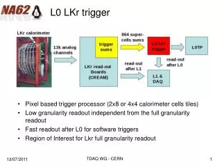
L0 LKr trigger • L0 LKr trigger (photon veto): cluster counting with 1-2 ns time resolution • Use existing hardware (NA48 and LHC) • Use the NA48 analog sums (2x8 cells) and cables replacing the “old” system with a new TELL1 based system A. Salamon – TDAQ WG - CERN
L0 LKr trigger • Use analog sums (2x8 cells) and all the cables already exist • Need to design the trigger processor LKr calorimeter read-out boards 864 analog channels analog sums L0 LKr trigger 13k analog channels CTP read-out after L0 DAQ A. Salamon – TDAQ WG - CERN
The TELL1 board • LHCb general purpose data acquisition board • 5 user programmable FPGAs, large on-board DDR memories • mezzanines for 4 x 1 gbit ethernet output analog mezzanine 16 x 10 bit digital mezzanine 12 x 16 bit Stratix FPGA 25k logic elem parallel bus 32 bit @ 160 MHz Stratix FPGA 40k logic elem output interface 4 x gbit ethernet A. Salamon – TDAQ WG - CERN
L0 LKr Trigger: architecture 13248 channels for the readout 864 channels (2x8 pixel supercells) for the trigger! FE boards: pulse reconstr (time, position, energy) Concentrator boards: merging, sorting 28 boards 5 boards ethernet1 meter TELL1 TELL1 32 supercells Ethernet mezz CTP ADC mezz 32 ch 24 ch • Need to design two mezzanines: • one FE + ADC mezzanine • one ethernet concentrator mezzanine • Two 9U crates! A. Salamon – TDAQ WG - CERN
L0 Lkr trigger: architecture Concentrator TELL1: merging, sorting 24 Front-End TELL1 1 analog sum (supercell) = 2x8 channels Front-End TELL1: pulse reconstruction (time, position and energy) 32 analog channels (1 channel = 2x8 liquid krypton cells analog sum) 28 FE TELL1s, 5 concentrator TELL1s, 32 supercells per TELL1 A. Salamon – TDAQ WG - CERN
Front-End ADC mezzanine 28 boards 5 boards • At the moment we are preparing a test stand using an existing LHCb mezzanine • New mezzanine later TELL1 TELL1 32 supercells ethernet Ethernet mezz CTP ADC mezz 32 ch 24 ch A. Salamon – TDAQ WG - CERN
FE to concentrator link I (new receiver) Front-End Concentr • Use existing gbit ethernet output mezzanine and design new ethernet receiver on the concentrator • Up to 24 ethernet input on the concentrator = 8 FE TELL1 (3 gbit per TELL1) • 24 ethernet connector is (mechanically) difficult but possible • Pros: lower design effort, bidirectional, added FPGA processing power on the receiver, flexible (same link for trigger and readout) • Cons: ethernet overhead, lower bandwidth TELL1 TELL1 Ethernet mezz ethernet Eth TX NEW!! A. Salamon – TDAQ WG - CERN
FE to concentrator link II (new TX) Front-End Concentr • Use existing optical receiver input mezzanine on the concentrator and design new ethernet + fiber optic transmitter • Cons: higher design effort, monodirectional, no added FPGA processing power on the receiver • Pros: no ethernet and added latency on the trigger path, higher bandwidth TELL1 TELL1 Optical mezz Eth + opt TX ethernet NEW!! A. Salamon – TDAQ WG - CERN
Pulse reconstruction (FE TELL1) Peak in space Peak finder (one channel) Peak in time Over threshold Peak processor(one channel) Parabolic fit 7 bit reconstructed fine time A. Salamon – TDAQ WG - CERN
Some plots (digital simulation!!!) 80 MHz sampling: 50 ps/bin full scale pulse -> 100 ps rms simulation simulation simulation simulation 40 MHz sampling: 100 ps/bin 1/40 full scale pulse + noise and jitter -> 700 ps rms A. Salamon – TDAQ WG - CERN
Front-End PP FPGA Fmax ~ 80 MHz 80% device usage on an EP1S25 multipliers, dividers: lot of Logic Elements A. Salamon – TDAQ WG - CERN
Front-End PP FPGA (new!!) multipliers, dividers: lot of Logic Elements RATE:5 samples @ 80 MHz = 16 MHz / PP FPGA A. Salamon – TDAQ WG - CERN
Hit rates (Front-End TELL1s) • Instantaneous design hit rate (Marco’s TDAQ note): 30 MHz • Rate in the central region (Giuseppe’s private communication): 3 times mean hit rate • Clusters of 256 liquid krypton cells (conservative) • All hits generate a shower (conservative) ( 30 MHz / 28 ) x 3 / 8 = 0.4 ( 30 MHz / 28 ) x 3 = 3.2 ( 30 MHz / 28 ) x 3 = 3.2 TOTAL RATE = 10.8 MHz vs 64 bit/cluster over 3 gbit eth links A. Salamon – TDAQ WG - CERN
Hit rates (PP FPGA = ¼ TELL1) • Same assumptions • Fast communication between PP FPGAs in the same TELL1 -> rate reduction ( 30 MHz / 28 ) x 3 / 8 = 0.4 ( 30 MHz / 28 ) x 3 / 4 = 0.8 ( 30 MHz / 28 ) x 3 /4 = 0.8 TOTAL RATE = 4.8 MHz vs 64 bit/cluster over 32b @ 160 MHz A. Salamon – TDAQ WG - CERN
Concentrator TELL1 (overlkap handling and hit rates) Maximum in the red area: the cluster is handled by the “red” TELL1 concentrator Maximum in the blue area: the cluster is handled by the “blue” TELL1 concentrator Double counting resolved at the level of the concentrator Only 4 over 8 Front-End TELL1s contribute to the output hit rate: OUTPUT RATE = (30 MHz / 28) x 3 x 4 = 12.9 MHz vs 64 bit/cluster over 3 gbit eth links A. Salamon – TDAQ WG - CERN
Lab tests: front-end TELL1 Arbitrary waveform generator: AWG2021 • We are preparing our test station for the Front-End mezzanine • AWG 2021 -> mezzanino analog sums -> cable -> TELL1 analog mezzanine -> TELL1 • Same signal in two different analog sums channels • time resolution rms = sigma(T1-T2)/sqrt(2) NA48 analog sum card TELL1 analog mezzanine A. Salamon – TDAQ WG - CERN
Lab tests: concentrator link • We are also working at the test station for our receiver • Use an altera development kit (Stratix II 60k Logic Elements) to validate and study the receiver ethernet A. Salamon – TDAQ WG - CERN
Time schedule • End of april – beginning of may: FE and ethernet link tests in the lab • Then start mezzanines desing • Then try to test the system on the liquid krypton (with LHCb ADC mezzanine first) A. Salamon – TDAQ WG - CERN