Download
1 / 15
150 likes | 320 Views
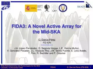
Integrated receivers for mid-band SKA. Suzy Jackson Engineer, Australia Telescope National Facility SKADS FP6 Meeting – Chateau de Limelette – 4-6 November, 2009. Talk overview. Mid band SKA receiver challenges ASKAP as a bridge to SKA RF-CMOS proof of concept receiver

E N D
Integrated receivers for mid-band SKA Suzy Jackson Engineer, Australia Telescope National Facility SKADS FP6 Meeting – Chateau de Limelette – 4-6 November, 2009
Talk overview • Mid band SKA receiver challenges • ASKAP as a bridge to SKA • RF-CMOS proof of concept receiver • Proposed integrated receiver for mid-band SKA CSIRO. Integrated receivers for mid-band SKA
Mid band PAF SKA (from a receiver viewpoint) Some large numbers: • Collecting area 1 km2 • Field of View 20 deg2 • Sensitivity 7000 m2/K • Survey Speed 1x10⁹ m4/K2.deg2 • Observing frequency ~500 – 2000 MHz • Processed Bandwidth >300 MHz • With dish diameter of 15 m • Number of dishes ~2500 • Focal Plane Phased Array ~400 elements • PAF data rate ~2.5 terabits/s • Total no. receivers required ~1 million CSIRO. Integrated receivers for mid-band SKA
Mid-band SKA receiver design challenges • Cost • €20 per receiver is ~ €20 million across the SKA • Size and weight • Total PAF weight limits of 200 kg (for ASKAP antenna) = 500 g per receiver • Power consumption • Dictated by weight – for example 1 kW per antenna = 2.5 W per receiver • Manufacturability & maintainability • Minimise number of parts • Performance • Low Tn • Wide RF and IF bandwidths • High dynamic range • RFI minimisation CSIRO. Integrated receivers for mid-band SKA
For SKA we want to go from this (ASKAP) Focus Cable wraps Pedestal LNA RF on copper A/D RF gain RF filters Frequency Conversion* *Dual conversion • Frequency conversion and sampler in the pedestal • Analog RF signal transmission over coaxial cable • Dual conversion (superheterodyne) receiver CSIRO. Integrated receivers for mid-band SKA
To this Focus Cable wraps Pedestal LNA Sampled IF on optical fibre Frequency Conversion* RF gain RF filters A/D *Direct conversion I&Q • Frequency conversion and sampler at the focus • Digital IF signal transmission over fibre directly to beamformer in antenna base or central site • Direct conversion I/Q receiver CSIRO. Integrated receivers for mid-band SKA
Proof-of-concept RF-CMOS receiver • Developed from 2004-2008 • 0.18µm RF-CMOS • 300 – 1700 MHz RF range • I/Q direct downconversion with 300 MHz (2 x 150 MHz) IF bandwidth – only one LO required and half ADC sample rate compared to conventional dual conversion scheme. • Dual 6 bit averaging termination flash ADCs • Noise cancelling input amplifier CSIRO. Integrated receivers for mid-band SKA
Proof-of-concept RF-CMOS receiver BASEBAND FILTERS LNA MIXERS QUADRATURE LO GEN ADCS RF FILTERS 3.5mm x 2.75mm CSIRO. Integrated receivers for mid-band SKA
Some proof-of-concept receiver results • RF CMOS performance quite good for mid-band use. • Tn ~180K (2dB) mid-band. Useable over 200 MHz – 2GHz. • Passive RF filters worked well despite low-Q bulk CMOS inductors. • Exceptional I/Q amplitude and phase match (0.1dB and 1 degree). • Isolation between LO and sample clock signals and RF very good, but some sample clock leakage still evident. • 5th harmonic of 256 MHz sample clock -78 dBm at RF input. • Minor ADC problems. • Clock to digital output noise coupling limits operation to 150 Msps. • 40dB SFDR achieved at 150 Msps. • Receiver showed the value of implementing the LNA as a separate circuit. • Reduction of LO and sample clock leakage. • Prevention of physical LNA heating from high power circuitry dissipation (ADC). • Fabrication of LNA in very fast CMOS/GaAs/InP process for lowest Tn. CSIRO. Integrated receivers for mid-band SKA
Proposed integrated receiver • Direct-downconversion I/Q architecture with divide-by-4 LO • Single out of band LO required • I/Q amplitude and phase match expected to be adequate to ensure 40 dB image suppression • Implementation of whole receiver from LNA output to ADC input • Including LO synthesiser and all filters • Minimal external components and cost • LNA off-chip for minimum Tn and maximum flexibility • Off-chip ADC to reduce development cost • Includes high power ADC drivers • Maximum flexibility • RF and baseband gain adjustable • RF filter selection switches (including bypass) • Baseband filter selection • Power level monitoring in RF and baseband • On-die temperature monitor CSIRO. Integrated receivers for mid-band SKA
Integrated receiver block diagram CSIRO. Integrated receivers for mid-band SKA
Target specification highlights • 250 MHz to 2500 MHz RF range. • Onboard by-passable RF filters – 700 MHz HP and 1200/1800 MHz LP. • I/Q direct quadrature down conversion • selectable instantaneous bandwidth from 150 to 600 MHz. • 40 dB dynamic range. • Due to tight I/Q amplitude and phase matching • Onboard LO synthesiser and ADC driver. • Plenty of RF and BB gain adjustment: • 34 – 59 dB RF gain range, 5 dB steps. • 8 – 20 dB BB gain range, 2 dB steps. • Compact 6mm square QFN package. • Low power (target ~2-3 W). CSIRO. Integrated receivers for mid-band SKA
Proposed initial Silicon-on-Sapphire development • 250 MHz to 2500 MHz RF range. • I/Q direct quadrature down conversion with selectable instantaneous bandwidth up to 600 MHz. • 40 dB dynamic range. • Onboard ADC driver. • 8 – 20 dB BB gain range, 2 dB steps. CSIRO. Integrated receivers for mid-band SKA
In context • Allows entire receiver to be housed behind feed • Lightweight and compact • Low power • Easily RFI shielded • Low cost (minimal connectors and cabling, low speed ADCs) • RF in, digital fibre out. Digital fibre Out Receiver cards LNAs PAF elements CSIRO. Integrated receivers for mid-band SKA
Contact Us Phone: 1300 363 400 or +61 3 9545 2176 Email: enquiries@csiro.au Web: www.csiro.au Thank you Australia Telescope National Facility Suzy Jackson Engineer – RF systems Phone: 02 9372 4359 Email: Suzy.Jackson@csiro.au Web: www.atnf.csiro.au/askap