Download
1 / 43
430 likes | 597 Views
Photonics and Future DATACENTER NETWORKS. Al Davis Hewlett Packard Laboratories & University of Utah 3 July, 2012. TODAy’s dominant information landscape. The dominant information appliance namely my primary computer is. My Other computer is. What’s the point?.

E N D
Photonics and Future DATACENTER NETWORKS Al Davis Hewlett Packard Laboratories & University of Utah 3 July, 2012
TODAy’s dominant information landscape • The dominant information appliance • namely my primary computer is
What’s the point? • End point is increasingly mobile • battery longevity both limited processing & limited memory/storage • memory != storage • typical driving applications access non-local information • Computation has to happen somewhere else • Information is also somewhere else • But hey – everything is on the internet • including refrigerators – this one is from LG • Key observation • “the network is the computer” – John Gage, Sun Microsystems employee #2 • The usual tower of Babel: datacenter, WSC, cloud, … • for now (datacenter = WSC) + SaaS = cloud • from an architectural perspective the difference is hard to spot
Hence: focus on the interconnect • Bill Clinton and Al Gore had the same focus • March 9, 1996 at Ygnacio Valley High School • bizarre: I was there as a sophomore in 33 years earlier when the school opened • today we’ll take a slightly more futuristic look
The first step • Information endpoint to the datacenter • 1st hop: wireless (802.11x, 3G) or wired to the “edge” • 2nd hop: telecom mostly fiber to the backbone fiber • 3rd hop: to the datacenter internet routers • Then there is a whole lot of interconnect in the datacenter • Response is then sent back via the reverse route • Key takeaway • the common transaction incurs a small amount of compute and a ton of communication
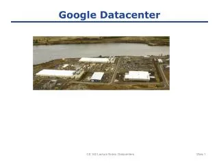
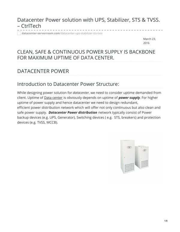
Today’s Data Centers • Mostly or all electrical • 50K+ cores already in play • larger configurations in the HPC realm • Configuration [3] • rows of racks • rack: .6 m wide, 1 m deep, 2 m high • each rack has 42 vertical 44.45 mm U slots, 175 kg rack, max loaded weight 900 kg • each RU holds 2 – 4 socket (multi-core) processors motherboards • # of cores growing – maybe even at Moore’s rate if you believe the pundits • cold and hot aisles (heat is a huge issue) – front side cold, back side hot • front to front and back to back row placement • >= 1.22 m cold row allows human access to blades but not the cables • >= .9 m hot row holds cables and is the key to CRAC heat extraction strategy • Communication distances in the data center • mm+ to 100+ m: between components on a board, intra-rack, or inter-rack
The Cable nightmare Source: random web photo’s Consider Hot Aisle Airflow The Ugly The Bad Fiber cables - The Best? The Good
Typical COMMERICAL DATACENTER Typical data center switch hierarchy Network bandwidth requirement increasing due to increasing node counts and line rates • doubling every 18 months? • future likely to be 100K sockets Core switches becoming increasing oversubscribed • leads to inefficiencies in resource scheduling New application loads place more stress on network • data centric workloads Aggregation EOR switches Core switches Top of Rack switches
Routing in the Data Center • Top of rack (TOR) and end of row (EOR) ethernet switches [3] • Core switches are even more expensive • large Cisco, ProCurve, etc. boxes (EOR prices +) • For HPC • prices are much higher due to router ASICS & better bisection topologies • bisection bandwidth improves significantly • important in the datacenter where high locality is not the predominant workload
EXAMPLE Data Centric workloads • Google system monitoring • disk and memory component error logging • new understanding of failure mechanisms • Financial trading • 350 billion transactions and updates per year • Sensor networks increased data glut • CENSE project
MaPREDUCE/HADOOP Another example of non-local communication patterns “Customers Who Bought This Item Also Bought……” • Sorting 1PB with MapReduce* • 4000 node cluster • 48000 disks • 1Petabyte of 100 byte records • Sort time 6 hours & 2 minutes. • *Google blog, November 2008 Computation Data REDUCE MAP Currently storage bandwidth limited – moving towards network bandwidth limited w/ increased SSD use Network intensive Storage intensive
DataCenter TRENDS [1] • Server count ~30M in 2007 • 5-year forward CAGR = 7% • EPA CAGR estimate is 17% • doesn’t account for server consolidation trend • “whacked on the Cloud” is a likely accelerant • Storage growth • 5-year forward CAGR = 52% • added 5 exabytes in 2007 - 105xLoC (the printed Library of Congress) • Internet traffic • 5-year forward CAGR = 46% (6.5 exabytes per month in 2007) • 650K LoC equivalents sent every month in 2007 • Internet nodes • 5-year backward CAGR = 27% • public fascination with mobile information appliances has accelerated this rate
Communication Estimates [1] • Server count growing slower than anything else • exponential communication growth per server in the data center • Estimate [1] (+/- 10x) • for every byte written or read to/from a disk • 10KB are transmitted over some network in the data center • for every byte transmitted over the internet • 1GB are transmitted within or between data centers • Estimate passes other litmus tests • increasing use of server consolidation & more cores/socket • increased use of virtualization in the data center • Clear conclusion • improving data center communication efficiency is likely more important than improving individual socket performance (which will happen anyway) • includes socket to socket & socket to main memory and storage
Other Data Center Challenges • Consume too much power, generate too much heat & C02 • 2007 EPA report to Congress – 2 socket server (2 cores/socket) • exponential server growth and increased energy costs BIG PROBLEM • Option: put them in a place where power is cheap and the outside air is cold 2006: 61 Pwh (doubled since 2000) doesn’t include telecom component $4.5B in electrical costs Total pwr/IT equip. pwr: 2 common, 1.7 good 1.2 claimed but hard to validate
Questionable Option! “In the search for cost attractive locations catering to power intensive industries, Iceland is the single country in the world that provides best in class environment conditions in combination with attractively priced green power supply” Price Waterhouse Coopers.
HPC Consolidation DRIVERS Exascale and Petascale Systems Kogge, et al., “ExaScale Computing Study”, 2008 • simple scaling of existing architectures would result in a 100MW system • likely maximum data center power 20MW DARPA UHPC program • one PETAFLOP performance • single air-cooled, 19-inch cabinet (or 1m3) • 57 kW including cooling. Grand challenge • how do we achieve these goals? • future datacenters with 100K nodes (each with 10’s to 100’s of cores) • O(103) increase in communication & memory pressure expected • without commensurate increase in communication latency & power consumption • shrinking transistors will help but not enough, the cm to 100m scale problem remains
Data Center NETWORK Req’s • High dimension networks • to reduce hop count • scalable without significant re-cabling • scale-out to accommodate more racks and rows • scale-up to higher performance blades • regularity will be important • minimize cable complexity • minimize number of cable SKU’s for cost purposes • enable adaptive routing to meet load balance demands • path diversity • increased availability and fault tolerance • High radix routers • to support high dimension networks & contain costs • bandwidth per port will need to scale over time • to accommodate increased communication pressure source: Luxtera
ITRS EYE CHART for INterconnect Indicative of severe problems ahead in the electrical domain
Electrical signaling & WIRES • Problems • power and delay fundamentally increase with length • improve delay with repeaters but requires even more power • signal integrity issues exist at all length scales • multi-drop busses make the problem much worse – hence they’re dead (DRAM exception noted) • pre- and post-emphasis circuits help but power is increased • ITRS predicts very slow growth of signal pin count & per pin bandwidth • bandwidth at the chip and board edge will also grow slowly • incommensurate with growth of computer power and communication pressure on the chip/board • Advantages • mature technology and volume production reduces cost • manufacturing and packaging have been optimized for electrical technology • “Always ride your horse in the direction it’s going” • Texas proverb • good questions: better horse? time to change direction?? • Conclusion • computation gets better with technology shrink but communication improves slowly or not at all in terms of BTE & delay.
RECENT SERDES PUBLICATIONS • Two classes of SerDes, short reach and long reach (memory & backplane) • Still seeing improvement in SerDes power (20% per year historically) • Numbers in system publications tend to be higher
Low Power SERDES COMPARISON • Output driver power not scaling • Output driver power becoming large fraction of total link power budget • Clocking and clock recovery still a significant fraction of power
Photonic signaling • Problems • immature technology • waveguides, modulators, detectors all exist in various forms in lab scale demonstrations • improvements likely but technology is here now – risky path: the lab to volume production & low cost • photonic elements don’t shrink with feature size • resonance properties a l a size • maintaining proper resonance requires thermal tuning • currently: cables, connectors, etc. all cost more than their electrical counterparts • Advantages • power consumption is independent of length for lengths of interest in the datacenter • due to the very low loss nature of the waveguides • energy consumption is at the EO or OE endpoints • relatively immune to signal integrity & stub electronic problems • buses are not a problem • built in bandwidth multiplier per waveguide: CWDM & DWDM • 10 Gbs/ldemonstrated - 4l now (MZ), doubling every 3 years likely, ~67l limit? • Common misconception – optical latency is faster • signal/electron mobility in copper ~= signals on a waveguide (free space, FR4 HMW, silicon)
Optical Losses 2cm of waveguide and 10m of fiber
INTEGRATED CMOS PHOTONCS POINT-To-pOINT power budget • 10Gbit/s per wavelength • 177fJ/bit assuming 32nm process • No clock recovery and latching - not directly comparable to electronic numbers • Tuning and laser power required when idle
Mellanox Infiniswitch IV • 36 ports @ 40Gbps or 12 ports @ 120Gbps. • 10Gbps per diff pair • 576 signal pins • 90W, 30% of which is IO Issues High performance switch - State of the Art Electronic Switch port count limited by pin count & IO power Additional external transceivers needed to drive >0.7m FR4 or 6m cable Increasing port bandwidth decreases port count EMI & signal integrity problematic
Improving DATA CENTER Networks • Step 1: Use optical cables • already in limited use • Step 2: Move optics into the core switch backplane (Interop 2011) • current core switch backplane limitations are hitting a rather hard wall • more power and higher cost are not feasible as bisection bandwidth demands advance • CWDM bandwidth scaling is an attractive proposition • Step 3: High radix router with photonics at the edge • silicon nano-photonics for the global interconnect • DWDM bandwidth scaling benefit • big technology jump to move photonics into the router chip • same device can be used in the TOR, EOR, and Core switches cost amortization • Step 4: Employ the photonic switch in regular high dimension networks • take advantage of regularity to improve routing, packaging, and data center layouts
Optical Bus Rx Rx Rx Rx Rx Rx Rx Rx Tx Tackling the bandwidth bottleneck with PHOTONICS On-chip interconnect Hybrid laser cable Silicon PIC Active cable
10x bandwidth scaling core switch requirement doubling every 18 months electronic technologies can no longer keep up 30% lower power high % of system power in interconnect Equivalent cost historically the main obstacle to adoption of optics Future Scaling VCSEL BW scaling 10G 25G single l CWDM 2 l 4 l optical backplane remains unchanged ALL Optically connected data center CORE switch
Characteristics • 64-128 DWDM ports • <400fJ/bit IO power • 160 - 640 Gbps per port Advantages INTEGRATED CMOS PHOTONIC SWITCH switch size unconstrained by device IO limits port bandwidth scalable by increasing number of wavelengths optical link ports can directly connect to anywhere within the data centre greatly increased connector density, reduced cable bulk
Minimize electronics Buffering & Routing Optical Cross Bar on Switch Die Other switches and terminals
Optical vs. Electrical Switch Overall Power in watts w.r.t Bandwidth Growth EE baseline based on the CRAY YARC Big benefit to bring optics to the router core edge Additional savings with single stage optical crossbar
Regular N-DimensionAL Networks • HyperX [5] • 2 simple examples • a regular flattened butterfly • also called a Hamming graph • Basic idea • fully connected in each dimension • one link to each mirror in allother dimensions • Regularity benefits • simple adaptive routing (DAL) • set L,S,K,T values to match needs • packaging & configuration
New network topologies – HyperX [5] • Direct network – switch is embedded with processors • avoids wiring complexity of central/core switches (e.g. fat trees) • much lower hop count than grids and torus • but many different interconnect lengths • Low hop count means:- • improved latency • lower power • less connectors • Huge packaging simplification • Anywhere in the data center in <1µs
Photonic HyperX package Datacenter is 3D – rack, row, other rows – no TOR
General Conclusions • Advances in electronics will continue BUT • processing benefits from these advances • data center communications will benefit but not as much • optics is the transport choice, electronics is the processor choice in an ideal world • NOTE: we don’t live in an ideal world • Complete change to optical communication will not happen in one step • e.g. multi-core was a tough bridge for merchant semiconductors to cross • argument with Albert Yu in 2000 but Kunle had presented the case well in 1996 • Tejas cancelled in 2004 – note the 8 year lag between research and industry adoption • industry momentum is significant but so is the research side • Power wall is here to stay (I don’t see the magic technology which moves the wall) • going green is not going to be easy if consumption is based on MORE • getting more performance for less power is problematic • replacing long wires with optical paths is a good idea • telecomm did this in the 80’s • definition of long for computing is changing however • maybe it should be relative to transistor speed
Photonics conclusions a somewhat personal view The switch to photonics is inevitable • the technology is already demonstrated in multiple labs around the world • however it’s not mature • costs need to come down • improvements will be made & a lot of smart people are making this happen The change will be gradual and a function of interconnect length • km scale – it’s already happened • 100m scale – in progress • m scale – just starting • cm scale – in the lab but relatively ready • mm scale – also in the lab but not ready for prime time The technology exists – the only barrier is cost • involves technology maturity, manufacturing infrastructure, and ultimately volume
The CATCH-22 • Photonic adoption is all about price • benefits are well known • cost is heavily influenced by volume production • volume production hasn’t happened yet • even though most devices require a CMOS compatible fab • data center market is there and growing • but it is cost sensitive • risky & new always costs and photonics is currently both • researchers continue to drive the photonic price down • It’s not a question of if – but when is the issue • NOTE!! • there are lots of other issues that this data center centric (duh! redundant) view didn’t cover • others in this session will cover these issues
HPL/ECL Moray McLaren (who provided some of these slides) – the rest is my fault Jung-Ho Ahn, Nate Binkert, Naveen Muralimanohar, Norm Jouppi, Rob Schreiber, Partha Ranganathan, Dana Vantrease … HPL/IQSL Ray Beausoleil, Marco Fiorentino, Zhen Peng, David Fattal, Charlie Santori, Di Liang (UCSB), Mike Tan, Paul Rosenberg, Sagi Mathai … Acknowledgments
For Further Study Some referenced in this presentation Greg Astfalk “Why optical data communications and why now?” Applied Physics A (2009) 95: 933-940. DOI 10.1007/s00339-009-5115-4. Terry Morris “Breaking free of electrical constraints” Applied Physics A (2009) 95:941-944. DOI 10.1007/s00339-009-5107-4. N. Farrington, E. Rubow, AminVahdat “Data Center Switch Architecture in the Age of Merchant Silicon” Hot Interconnects 2009. A. Greenberg et. al “The Cost of a Cloud: Research Problems in Data Center Network” DOI 10.1.1.149.9559. J-H Ahn et. al “HyperX: Topology, Routing, and Packaging of Efficient Large-Scale Networks” Supercomputing 2009.