Download
1 / 59
740 likes | 2.7k Views
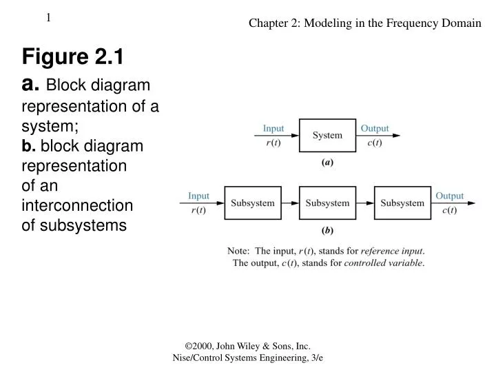
Figure 2.1 a. Block diagram representation of a system; b. block diagram representation of an interconnection of subsystems. Table 2.1 Laplace transform table. Table 2.2 Laplace transform theorems. Figure 2.2 Block diagram of a transfer function.

E N D
Figure 2.1 a.Block diagramrepresentation of a system;b. block diagramrepresentationof aninterconnectionof subsystems ©2000, John Wiley & Sons, Inc. Nise/Control Systems Engineering, 3/e
Table 2.1Laplace transform table ©2000, John Wiley & Sons, Inc. Nise/Control Systems Engineering, 3/e
Table 2.2Laplace transform theorems ©2000, John Wiley & Sons, Inc. Nise/Control Systems Engineering, 3/e
Figure 2.2 Block diagram of a transfer function ©2000, John Wiley & Sons, Inc. Nise/Control Systems Engineering, 3/e
Table 2.3Voltage-current, voltage-charge, and impedance relationships for capacitors, resistors, and inductors ©2000, John Wiley & Sons, Inc. Nise/Control Systems Engineering, 3/e
Figure 2.3RLC network ©2000, John Wiley & Sons, Inc. Nise/Control Systems Engineering, 3/e
Figure 2.4Block diagram of series RLC electrical network ©2000, John Wiley & Sons, Inc. Nise/Control Systems Engineering, 3/e
Figure 2.5Laplace-transformednetwork ©2000, John Wiley & Sons, Inc. Nise/Control Systems Engineering, 3/e
Figure 2.6a. Two-loop electricalnetwork;b. transformedtwo-loop electricalnetwork;c. block diagram ©2000, John Wiley & Sons, Inc. Nise/Control Systems Engineering, 3/e
Figure 2.7Block diagram of the network of Figure 2.6 ©2000, John Wiley & Sons, Inc. Nise/Control Systems Engineering, 3/e
Figure 2.8Transformednetwork readyfor nodal analysis ©2000, John Wiley & Sons, Inc. Nise/Control Systems Engineering, 3/e
Figure 2.9Three-loopelectrical network ©2000, John Wiley & Sons, Inc. Nise/Control Systems Engineering, 3/e
Figure 2.10a. Operationalamplifier;b. schematic for aninverting operationalamplifier; c. inverting operational amplifier configured for transfer function realization. Typically, the amplifier gain, A, is omitted. ©2000, John Wiley & Sons, Inc. Nise/Control Systems Engineering, 3/e
Figure 2.11Inverting operationalamplifier circuit for Example 2.14 ©2000, John Wiley & Sons, Inc. Nise/Control Systems Engineering, 3/e
Figure 2.12General noninvertingoperational amplifiercircuit ©2000, John Wiley & Sons, Inc. Nise/Control Systems Engineering, 3/e
Figure 2.13Noninvertingoperational amplifiercircuit forExample 2.15 ©2000, John Wiley & Sons, Inc. Nise/Control Systems Engineering, 3/e
Figure 2.14Electric circuit forSkill-AssessmentExercise 2.6 ©2000, John Wiley & Sons, Inc. Nise/Control Systems Engineering, 3/e
Table 2.4Force-velocity, force-displacement, and impedance translational relationshipsfor springs, viscous dampers, and mass ©2000, John Wiley & Sons, Inc. Nise/Control Systems Engineering, 3/e
Figure 2.15a. Mass, spring, and damper system; b. block diagram ©2000, John Wiley & Sons, Inc. Nise/Control Systems Engineering, 3/e
Figure 2.16a. Free-body diagram of mass, spring, and damper system;b. transformed free-body diagram ©2000, John Wiley & Sons, Inc. Nise/Control Systems Engineering, 3/e
Figure 2.17a. Two-degrees-of-freedom translationalmechanicalsystem8;b. block diagram ©2000, John Wiley & Sons, Inc. Nise/Control Systems Engineering, 3/e
Figure 2.18a. Forces on M1 due only to motion of M1b. forces on M1 due only to motion of M2c. all forces on M1 ©2000, John Wiley & Sons, Inc. Nise/Control Systems Engineering, 3/e
Figure 2.19a. Forces on M2 due only to motion of M2;b. forces on M2due only to motionof M1;c. all forces on M2 ©2000, John Wiley & Sons, Inc. Nise/Control Systems Engineering, 3/e
Figure 2.20Three-degrees-of-freedomtranslationalmechanical system ©2000, John Wiley & Sons, Inc. Nise/Control Systems Engineering, 3/e
Figure 2.21Translationalmechanical systemfor Skill-AssessmentExercise 2.8 ©2000, John Wiley & Sons, Inc. Nise/Control Systems Engineering, 3/e
Table 2.5Torque-angular velocity, torque-angular displacement, and impedancerotational relationships for springs, viscous dampers, and inertia ©2000, John Wiley & Sons, Inc. Nise/Control Systems Engineering, 3/e
Figure 2.22a. Physical system; b. schematic; c. block diagram ©2000, John Wiley & Sons, Inc. Nise/Control Systems Engineering, 3/e
Figure 2.23a. Torques on J1due only to themotion of J1b. torques on J1due only to themotion of J2c. final free-bodydiagram for J1 ©2000, John Wiley & Sons, Inc. Nise/Control Systems Engineering, 3/e
Figure 2.24a. Torques on J2due only to themotion of J2;b. torques on J2due only to themotion of J1c. final free-bodydiagram for J2 ©2000, John Wiley & Sons, Inc. Nise/Control Systems Engineering, 3/e
Figure 2.25Three-degrees-of-freedom rotationalsystem ©2000, John Wiley & Sons, Inc. Nise/Control Systems Engineering, 3/e
Figure 2.26Rotational mechanical system for Skill-AssessmentExercise 2.9 ©2000, John Wiley & Sons, Inc. Nise/Control Systems Engineering, 3/e
Figure 2.27A gear system ©2000, John Wiley & Sons, Inc. Nise/Control Systems Engineering, 3/e
Figure 2.28Transfer functions for a. angular displacement in lossless gears and b. torque in lossless gears ©2000, John Wiley & Sons, Inc. Nise/Control Systems Engineering, 3/e
Figure 2.29a. Rotationalsystem drivenby gears;b. equivalent system at the output after reflection of input torque;c. equivalent system at the inputafter reflection ofimpedances ©2000, John Wiley & Sons, Inc. Nise/Control Systems Engineering, 3/e
Figure 2.30a. Rotational mechanical system with gears;b. system after reflection of torques and impedances to the output shaft;c. block diagram ©2000, John Wiley & Sons, Inc. Nise/Control Systems Engineering, 3/e
Figure 2.31Gear train ©2000, John Wiley & Sons, Inc. Nise/Control Systems Engineering, 3/e
Figure 2.32a. System using a gear train;b. equivalent system at the input;c. block diagram ©2000, John Wiley & Sons, Inc. Nise/Control Systems Engineering, 3/e
Figure 2.33Rotational mechanical system with gears for Skill-Assessment Exercise 2.10 ©2000, John Wiley & Sons, Inc. Nise/Control Systems Engineering, 3/e
Figure 2.34NASA flightsimulatorrobot arm withelectromechanicalcontrol systemcomponents © Debra Lex. ©2000, John Wiley & Sons, Inc. Nise/Control Systems Engineering, 3/e
Figure 2.35DC motor:a. schematic12;b. block diagram ©2000, John Wiley & Sons, Inc. Nise/Control Systems Engineering, 3/e
Figure 2.36Typical equivalentmechanical loading on a motor ©2000, John Wiley & Sons, Inc. Nise/Control Systems Engineering, 3/e
Figure 2.37DC motor driving a rotational mechanical load ©2000, John Wiley & Sons, Inc. Nise/Control Systems Engineering, 3/e
Figure 2.38Torque-speed curves with an armature voltage, ea,as a parameter ©2000, John Wiley & Sons, Inc. Nise/Control Systems Engineering, 3/e
Figure 2.39a. DC motor and load;b. torque-speed curve;c. block diagram ©2000, John Wiley & Sons, Inc. Nise/Control Systems Engineering, 3/e
Figure 2.40Electromechanical system forSkill-Assessment Exercise 2.11 ©2000, John Wiley & Sons, Inc. Nise/Control Systems Engineering, 3/e
Figure 2.41Development ofseries analog:a. mechanical system;b. desired electricalrepresentation;c. series analog;d. parameters forseries analog ©2000, John Wiley & Sons, Inc. Nise/Control Systems Engineering, 3/e
Figure 2.42Series analog of mechanical system of Figure 2.17(a) ©2000, John Wiley & Sons, Inc. Nise/Control Systems Engineering, 3/e
Figure 2.43Development ofparallel analog:a. mechanical system;b. desired electricalrepresentation;c. parallel analog;d. parameters forparallel analog ©2000, John Wiley & Sons, Inc. Nise/Control Systems Engineering, 3/e
Figure 2.44Parallel analog ofmechanical systemof Figure 2.17(a) ©2000, John Wiley & Sons, Inc. Nise/Control Systems Engineering, 3/e
Figure 2.45a. Linear system;b. nonlinear system ©2000, John Wiley & Sons, Inc. Nise/Control Systems Engineering, 3/e