Download
1 / 20
210 likes | 393 Views
P11251: Side Entry Agitator Test Stand. https://edge.rit.edu/content/P11251/public/Home. MSD II: Project Review. Friday, May 13, 2011 @ 10:00-11:00AM SPX Corporation/LIGHTNIN MIXERS. A100. A312. Project Team/Attendees. Project Sponsor : Richard O. Kehn - "ROK"

E N D
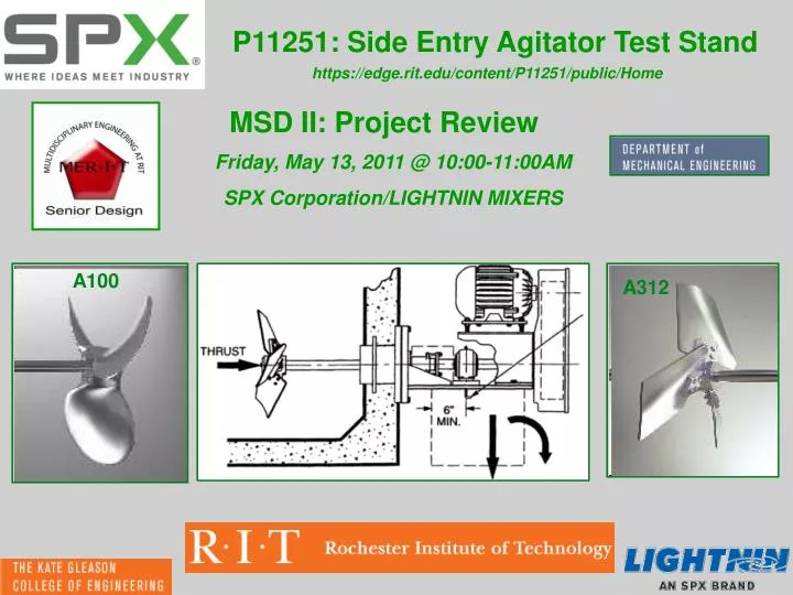
P11251: Side Entry Agitator Test Stand https://edge.rit.edu/content/P11251/public/Home MSD II: Project Review Friday, May 13, 2011 @ 10:00-11:00AM SPX Corporation/LIGHTNIN MIXERS A100 A312
Project Team/Attendees Project Sponsor : Richard O. Kehn - "ROK" Senior Technologist - Mixing SPX Flow Technology MSD Team Guide: William J. Nowak Principal Engineer, BGO/XIG/XRCW/OSL/Media & Mechatronic SystemsXerox Corporation Team P11251: Kurt Lutz: P.M./(Measurement System w/ Integration) Dennis Beatty: (Fluid-Tight Sealing Structure) Joseph Bunjevac: (Physical Structure w/ Adjustability) Daniel Geiyer: (Measurement System w/ Integration) Gregory McCarthy: Scribe/(Motor/Shaft/Coupling Integration)
Meeting Agenda Time Frame • Project Background & Description 10:05-10:10 • Customer Requirements 10:10-10:12 • Engineering Specifications 10:12-10:15 • Concept Summary 10:15-10:20 • System Architecture 10:20-10:30 • Physical Structure • Sealing System • Shaft, Motor & Impeller Integration • Measurement System with Hardware Integration • Load Cells: Thrust & FF Measurement • LabVIEW, Motor Torque & RPM • Design Summary 10:30-10:35 • System Testing Schedule & Results 10::35-10:40 • Objective Project Evaluation: Success and Failure 10:40-10:45 • Opportunities/Suggestions for Future Work 10:50-10:55 • Lessons Learned 10:55-11:00 • Acknowledgements
Project Background & Description Mission Statement: To create a side entry agitator test stand that allows the user to measure and calculate axial and tangential components of fluid forces, torque, and impeller speed on the motor, impeller, and shaft, incorporating a wide range of adjustable parameters. A100 A312 Side Entry Agitator Top Entry Application
Customer Requirements Four Most Important Customer Needs: • Fluid Tight Seal • Calibration Incorporation • Tangential Fluid Forces • Fluid Thrust Force
Engineering Specifications • Most important specs were deemed first priority. • Ability to measure desired forces effectively. • Designed to meet travel and angle requirements. • Able to be calibrated and give repeatable results. • Must have low rate of leakage or all else is moot.
Concept Summary Subsystem Selection Existing Technology Vs Innovative Technology System Interface Selection
System Architecture Sprocket for lead screw sync Ratcheting Handles Slotted support for vertical angle adjustment Handle for horizontal angle adjustment Ball transfers for horizontal travel Horizontal Angle indicator Vertical position indicator
System Architecture [Physical Structure] • Vertical height and vertical angle integrated • Horizontal pivot point at tank wall • Smooth adjustment of horizontal angle • Easy to read position indicators • Directional ratchets on lead screws for height adjustment • FOS > 4
System Architecture [Sealing System] • Rubber Bellows to allow for all of the motion necessary. • Mechanical Seal for less drag. • Support Rods to keep the Mechanical Seal parallel to the measurement plates and to prevent rotational movement. Tank Wall Rubber Bellows Mechanical Seal Tank Flange Gasket Gasket Support Rod Mount Seal Flange Support Rod
System Architecture [Shaft, Motor & Impeller Integration] • 5HP, 1800RPM AC Motor, VFD Controlled • Stepped Shaft to handle loading • Rigid Shaft Coupling for consistent measurement • Minimum FOS = 1.7 using worst case analysis SMI SYSTEM MODEL Acceptable Motor Bearings & Construction RIGID Shaft Coupling Ø1.375 Shaft (Matched Output Shaft) Axial & Radial Loads Ø.75” for Impeller Integration Weight & FF Torque Speed Rating Critical Speed Thrust 5HP AC Motor IP 55 Rating 316 SS (2) Piece Coupling 316 SS Stepped Shaft G McCarthy & Manuf. CAD Models
System Architecture [Tangential and Axial Force Measurement] • Load Cell Mount Plate and Motor Mount Plates designed for minimum deflection (less than .001”) • Support pins for easy assembly and overload protection for the 1000 lb capacity load cells • Support Pins to eliminate non-axial forces seen by the Load Cells • Support Pin Bushings for limited friction Load Cell Mount Plate Support Pin Motor Mount Plate
System Architecture [LabVIEW, Motor Torque & RPM] Signal Amplifier • RPM dialed in as constant • Torque measured from VFD, input to LabView • Load cell signal acquired and converted to axial and tangential forces • Data written to spreadsheet file for future manipulation in Matlab and Excel Load Cell DAQ System
Design Summary • Breaking this system into Sub-Systems allows the opportunities for future revisions and development of a single system without affecting the entire system. • The use of simple technology with current hardware eliminates the need for new equipment with an added learning curve. • Design above set engineering specifications to compensate for unforeseen demands. • Single control for independent adjustability. • A fully integrated system limits the the demands on human resources while exceeding the expectations of the customer • Provide a full product with all required materials focusing on the use of standard tools
System Testing Schedule Intended Tests: Completed Tests: Tests to Finish:
Objective Project Evaluation [Success/Failure] • Successes • System fully designed to meet 85% of all specifications • Load cells/DAQ communication • Seal system met requirements • Horizontal travel operates smoothly • Failures • Ordering incorrect parts • Purchases not made early enough • Deliver fully assembled system on time [5/17/11]
Opportunities/Suggestions For Future Work • Perform in-tank testing to evaluate design considerations • Perform multiple tests to prove reliability & repeatability of system • Compare new system data to historical data, equations, & calculations • Optimize design for more efficient functionality • Improve VI capabilities for data acquisition and handling • Add filtering capabilities to make collected data more meaningful • Utilize full functionality & programmability of VFD motor control
Lessons Learned • Do not under estimate the simplicity of the design in manufacturing parts • Anticipate vendors and/or suppliers will not be on time • Build flexibility into project plan to accommodate these anticipations • Anticipate delays amongst team members and sub-system development • Utilize local vendors as much as possible, promote local business • Maximize utilization of RIT’s machining resources • Possible outsourcing of complex machining • Establish design “lock points” where everyone agrees upon system design & functionality • Increase “uniform communication”: online note board/to do list/checklist • Introduce RIT’s purchasing system prior to beginning MSD II • Track documentation of: ordered, shipped, & received parts more effectively
Acknowledgements • Special Thanks to: • Richard Kehn, Bernie Gigas & Tom Taylor, on behalf of SPX, for making this project possible • Bill Nowak for providing guidance & field experience throughout the project • Prof. John Wellin for LabView & DAQ input • Dr. Kempski & Dr. Bodeo for technical advising & theoretical input • Dave Hathaway, Steve Kosciol, & Rob Kraynik for their assistance with machining, welding, and constructing the system. • John Bonzo & the Brinkman Lab for CNC machining select parts • Ryan Crittenden & FMS for electrical advise and wiring to NYS Code