Download
1 / 12
120 likes | 214 Views
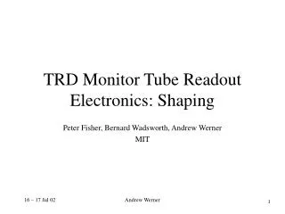
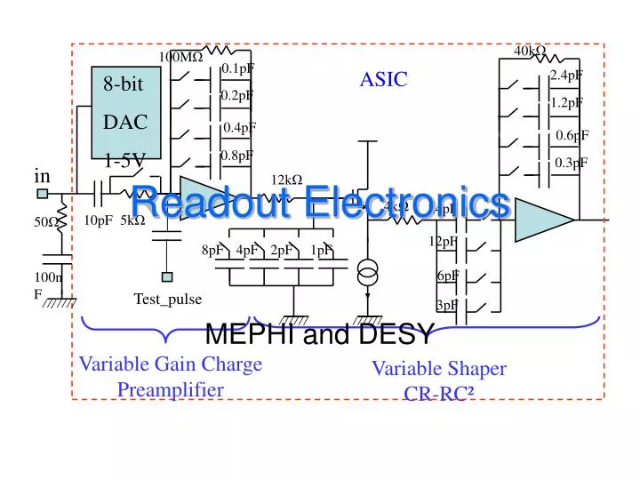
40k Ω. 100M Ω. 0.1pF. ASIC. 2.4pF. 8-bit DAC 1-5V. 0.2pF. 1.2pF. 0.4pF. 0.6pF. 0.8pF. 0.3pF. in. 12k Ω. 4k Ω. 24pF. 10pF. 5k Ω. 50 Ω. 12pF. 8pF. 4pF. 2pF. 1pF. 6pF. 100nF. Test_pulse. 3pF. Variable Gain Charge Preamplifier. Variable Shaper CR-RC².

E N D
40kΩ 100MΩ 0.1pF ASIC 2.4pF 8-bit DAC 1-5V 0.2pF 1.2pF 0.4pF 0.6pF 0.8pF 0.3pF in 12kΩ 4kΩ 24pF 10pF 5kΩ 50Ω 12pF 8pF 4pF 2pF 1pF 6pF 100nF Test_pulse 3pF Variable Gain Charge Preamplifier Variable Shaper CR-RC² Readout Electronics MEPHI and DESY
Outline • Measurement of main characteristics of ASIC’s PreAmp • ASIC temperature dependence • Measurement of DAC characteristics • Safety operation of SiPM with ASIC in case of emergency call 3563 (S. Karakash) MEPhI and DESY
ASIC schematic 40kΩ 100MΩ 0.1pF ASIC 2.4pF 8-bit DAC 1-5V 0.2pF 1.2pF 0.4pF 0.6pF 0.8pF 0.3pF in 12kΩ 4kΩ 24pF 10pF 5kΩ 50Ω 12pF 8pF 4pF 2pF 1pF 6pF 100nF Test_pulse 3pF Variable Gain Charge Preamplifier Variable Shaper CR-RC² 1 pF MEPhI and DESY
Linearity test } Cin =68pF → signal is SiPM like: ~5ns risetime ~30ns full signal time Calibration mode: G=0,1pF, T=min, R(10k)=OFF; Physic mode: G=0,5pF, T=max, R(10k)=ON; MEPhI and DESY
Input Noise measurement • „input“ noise = output noise / gain • Should be independent on preamplifier and shaper • Observed proportionality of input noise to gain & shaping time • need to understand MEPhI and DESY
Physic mode Calibration mode MEPhI and DESY
Test input Physic mode [DAC=OFF, G=0,5pF, T=max, R(10k)=ON] Calibration mode [DAC=OFF, G=0,1pF, T=min, R(10k)=OFF] MEPhI and DESY
1.30V Simulation of PreAmp signal Cf=0.1p 4,9 instead 8 0.2p 3,25 instead 4 0.4p 1.25V 0.8p 1,9 instead 2 1 1.225 V 1.20V 1.15V 0s 100ns 150ns V(OUT_SH) Time • The simulation of the dependency of output pulse has showed that existing Preamp parameters without feedback (Gain = 1500 and f1 = 1GHz ) are not enough to provide needed signal amplification. We can see the output pulses expected for different values of feedback capacitance Cf. One can see that for given values Gain and f1 the Preamp’s gain is increased much slowly (factor 4,9 instead 8). • It is recommended to increase the Gain value of at least one order of magnitude. MEPhI and DESY
Important data and conclusions • Peak position does not depend on temperature • Pedestal depend on T ~1,5 mV/0K • Dependency Gain factor from temperature • Noise has the same T dependence as gain MEPhI and DESY
Dependency DAC voltage and noise from temperature • Setting voltage depends on temperature DV/DT~3mV/oK • DACNoise depends on temperature ~ +2% MEPhI and DESY
Current measurements of DAC HV PS ON & LV PS ON Working SiPM: I = 0.2-2 uA -- internal DAC R 15-17 kOhm Voltage in input of ASIC will be acceptable Shortened SiPM: I < 0.7 mA -- internal DAC R ~300 Ohm Acceptable voltage at ASIC input HV PS ON & LV PS OFF : Working SiPM: I = 0.2-2 uA – internal DAC R ~ 140 kOhm U (in input ASIC) ~ 0,7V Shortened SiPM: I < 0.7 mA – internal DAC R ~ 10 kOhm U (in input ASIC) ~ 0,7V MEPhI and DESY
Summary & Questions & Remarks • ASIC’s PreAmp & ASIC’s DAC have good thermal stability in both mode. • But it is still necessary to stabilize temperature around HAB in the range +/- 3 degrees • We cannot use test input for T monitoring of electronics over a large T range • need to stabilize temperature • It is recommended to increase the ASIC gain factor by one order of magnitude in the next design allows to use SiPM with smaller gain & reduces T dependency • We recommend to decouple DAC and PreAmplifier inside ASIC and use separately DAC output and PreAmplifier input for each channel. • It makes the system more flexible and gives a possibility to use an external circuit for DAC noise filtering • We suggest to make the ASIC test input completely identical to signal input perfect monitoring under change of external conditions (ToC etc.) MEPhI and DESY