Download
1 / 95
1.52k likes | 2.53k Views
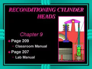
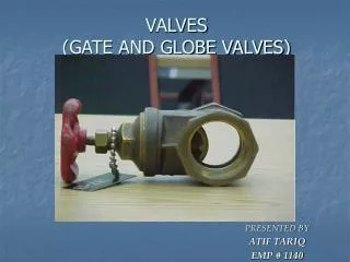
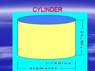
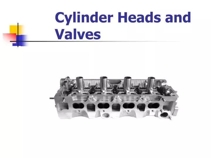
Cylinder Heads and Valves. Cylinder Heads. Purpose – regulates the air/fuel in/out of the engine Construction Cast Iron Cast Aluminum Overhead valve heads incorporate: Valves @ related components Coolant passages Valve operation mechanism(s). Cylinder Heads.

E N D
Cylinder Heads • Purpose – regulates the air/fuel in/out of the engine • Construction • Cast Iron • Cast Aluminum • Overhead valve heads incorporate: • Valves @ related components • Coolant passages • Valve operation mechanism(s)
Cylinder Heads • Overhead camshaft heads will also incorporate: • Camshaft(s) • Rocker arms or followers
Hemispherical Cylinder Heads • Hemi – a Chrysler term for a symmetrical cylinder design. • Typically valves would be positioned directly opposite in the head with (ideally) a spark-plug positioned between them. • Modern designs my incorporate two spark-plugs. • NOT exclusive to Chrysler!
Cylinder Heads • Cross flow head design– the practice of placing the intake port and the exhaust port on opposite sides of the cylinder head.
Traditional Arrangement • Traditionally, combustion chambers would have one exhaust valve and one intake valve.
Multiple Valves • Four valves per cylinder – two exhaust and two intake valves. • Pentroof design – each pair of valves are inline
Intake - Exhaust Ports • The passageways in the cylinder head that lead to/from the combustion area. • Intake: • Larger ports = more airflow • Smaller ports = better velocity for low RPM operation • Longer ports = better atomization on carb and TBI • Shorter ports = denser A/F charge
Gasket Matching Using an intake gasket as a template to “port” the heads
Coolant Passages • Coolant travels through the cylinder head from the engine block. • Cylinder head gaskets may be designed to restrict coolant flow rate. • Often a source for corrosion and leakage.
Cylinder Head Removal • All aluminum cylinder heads should be removed with a reverse torque procedure.
Cylinder Head Resurfacing • Heads should be checked in five places for warpage, distortion, bends or twists. • Check manufacturers specifications, maximum tolerances usually around .004”.
Valve Guides • The “bore” in the cylinder head that supports and controls lateral valve movement. • Often integral on cast iron heads • Always an insert on aluminum heads
Valve Guides • Steel insert on aluminum heads
Valve Stem To Guide Clearance • Always check manufacturers specs • Intake valve will typically be .001 to .003” • Exhaust valve will typically be .002 to .004” • The exhaust valve stem clearance will generally be greater due to the higher operating temperatures.
Valve Guide Wear • Guides are checked in 3 locations • With a small-hole gauge then measured with a micrometer • Or checked with a small bore gauge
Valve Stem Wear • Measured with a micrometer at three separate locations.
Valve Stem To Guide Clearance Correction • Oversized Valve Stems– the guide is reamed to accept a larger stem. • Must use a valve with an oversized stem. • Reduced flow rate
Valve Stem To Guide Clearance Correction • Valve guide Knurling– a tool is driven into the guide that displaces metal thus reducing the inside diameter of the guide. (p. 340-341) • The guide is then reamed to attain proper clearance • Not recommended for clearances +.006
Valve Stem To Guide Clearance Correction • Valve guide replacement– (insert) the old guide is driven out and a replacement guide is driven in. • The guide may require reaming to achieve proper stem to guide clearance.
Valve Stem To Guide Clearance Correction • Valve Guide Inserts– (integral) the old guide is drilled oversized and inserts are installed. • Pressed fit • May be steel or bronze
Intake & Exhaust Valves • Automotive valves are of a poppet valve design.
Valve Materials • Stainless steel • May be aluminized to prevent corrosion • Aluminum • Hardened valve tips and faces • Stellite (nickle, chromium and tungsten) valve tips and faces • Stellite is non-magnetic
Valve Materials • Sodium-filled – a hollow stem filled with a metallic sodium that turns to liquid when hot (heat dissipation). • Exhaust valves are largely comprised of a chromium material (anti-oxidant) with nickel, manganese and nitrogen added. • May be heat-treated • May be of a two-piece design
Intake & Exhaust Valves • Valves are held into place by a retainer and keeper. • Aluminum heads will have a separate spring seat (iron heads will have integral seats)
Valve Seats • Integral seats – cast iron heads – induction-hardened to prevent wear • Valve seat inserts – typically aluminum heads – hardened seats are pressed into the heads
Valve Inspection • Valve tips should not be mushroomed • Most valve damage is due to excessive heat or is debris “forged”. • Replace any valve that appears Burnt • Cracked • Stressed • Necked
Valve Springs • A spring “winds-up” as it is compressed – this causes the valve to rotate. • May have inside dampers to control vibration. • Springs are camshaft specific. • Squareness (+ (-) .060) • Spring free height (+ (-) .060) • Compressed force (+ (-) 10%) • Valve open height • Valve closed height
Valve Seat Reconditioning • The angle of the valve seat is reconditioned. • Often 3 stage (triple-angle) to promote flow and overhang. • May be done with “seat stones” • May also be done with a SERDI type set-up where the 3 angles are cut with one cutting tip.
Valve Reconditioning • The stem is lightly chamfered to insure proper fit in the valve grinder. • The face of the valve is reground using a valve grinder. (45 or 30 degrees typical). • Interference angle – the practice of grinding the face 1degree less than the seat angle. • The valve must retain its “margin” area. • the stem should be ground ½ the value that the face was ground with nonadjustable rockers.
Valve Lapping • The use of valve compound and a suction cup stick to establish a pattern • May be done to “freshen” the seat and face areas
Valve Lapping • The use of valve compound and a suction cup stick to establish a pattern • May be done to “freshen” the seat and face areas • Also used to check the contact pattern while cutting valve seats All compound must be removed prior to service
Valve Seals • Valve Seals are designed to allow sufficient lubrication of the valve stem/guide and also control oil consumption. • Umbrella seals – hold tightly onto the valve stem • Positive valve stem seals – hold tightly onto the guide • O-rings – controls oil between the spring and retainer
Checking Installed Height • If a valve seat and face are cut the valve will sit lower in the head. • The result is that the stem will sit higher on the top of the head. • This will cause the springs to have improper tension. • Installed height is measured and shims are added under the spring to compensate.
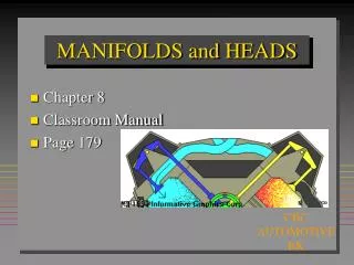
Camshaft The camshaft rotates ½ times the crankshaft – or – once per four-cycle stroke. • The camshaft may operate the: • Valve train • Mechanical fuel pump • Oil pump • Distributor
Camshaft • Major function - operate the valve train. • The lobes on the cam open the valves against the pressure of the valve springs. • Bearing journal can be internally or externally lubricated (oiled).
When installing externally oiled cam bearings it is essential that the holes in the bearings lineup with the oil passages in the block
Camshaft • Pushrod engines have the cam located in the block. • Cam is supported by the block and the cam bearings.
Camshaft • Cam may or may not be held in place by a thrust plate. • Most roller camshafts are held in by a thrust plate.
Overhead Camshafts • Overhead camshafts are either belt or chain driven and are located in the cylinder heads.
Overhead Camshafts • Will use one of the following: • Cam followers • Rocker arms • May have a one piece lifter – rocker design • A bucket design