Download
1 / 183
1.85k likes | 2.25k Views
Understand short-term, long-term, and surface properties of plastics, including tensile strength, modulus, and more. Learn about stress-strain curve, test methods, and factors influencing properties.

E N D
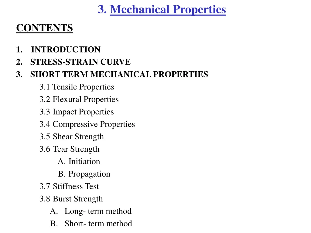
3. Mechanical Properties CONTENTS 1.INTRODUCTION 2.STRESS-STRAIN CURVE 3.SHORT TERM MECHANICAL PROPERTIES 3.1 Tensile Properties 3.2Flexural Properties 3.3Impact Properties 3.4Compressive Properties 3.5Shear Strength 3.6Tear Strength A.Initiation B.Propagation 3.7Stiffness Test 3.8Burst Strength A.Long- term method B.Short- term method
4.LONG TERM PROPERTIES 4.1Creep Properties 4.2Stress Relaxation 4.3Fatigue Resistance 5. SURFACE PROPERTIES 5.1 Abrasion Resistance. A.Transparent Plastics B.Flat specimens 5.2 Hardness Test 5.3 Co-efficient of Friction
Topics Covered 1.Introduction 2.Definition 3.Significance 4.Test Method 5.Specimen Preparation and Condition 6.Test Procedure 7.Observation / Calculation/Result 8.Formula 9.Factors Influencing 10.Test Results 11.Safety Precautions 12.References
1. INTRODUCTION The mechanical properties are the most important properties because all service conditions and the majority of end-use applications in involve some degree of mechanical loading. The material selection for a variety of applications is quite often based on mechanical properties such as tensile strength, modulus, elongation and impact strength. Although the voluminous data on these engineering properties are available, this is still not sufficient in view of the rapid development of new polymers and their formulations. Available data on mechanical properties are not sufficient for material selection since these are dependent on temperature, humidity, time, loading conditions, rate of loading etc. The mechanical properties of plastics can be broadly classified as short-term, long-term and surface properties. The short-term properties are measured at a constant rate of stress or strain different modes like tension, compression, flexural, shear etc. The long-term properties are measurements of deformation or stress decay with respect to time in static conditions e.g. creep and stress relaxation. The mechanical properties such as tensile strength, modulus, elongation and impact strength are normally derived from the technical literature. Definition of these properties are as follows:
a)Stress: The force applied to produce deformation in a unit area of a test specimen. Stress is a ratio of applied load to the original cross sectional area expressed in lbs/in2. b)Strain: The ratio of elongation to the gauge length of the test specimen, or simply stated, change in length per unit of the original length. It is expressed as the dimensionless quantity. c) Gauge Length:The original length between two marks on the test piece over which the change in length is determined. d)Percentage Elongation: The increase in the length of a specimen produced by a tensile load. e)Percentage Elongation at Yield:The percentage elongation produced in the gauge length of the test piece at the yield stress. f)Percentage Elongation at break, or at maximum load:The elongation at break, or at maximum load, produced in the gauge length of the test piece, expressed as a percentage of the gauge length. a) g) Elongation:The increase in the length of a specimen produced by a tensile load. h) Yield point: The first point of stress-strain curve at which an increase the strain occurs without the increase in stress.
i)Yield strength:The stress at which a material exhibits a specified limiting deviation from the proportionality of stress to strain. j)Proportional limit: The greatest stress at which a material is capable of sustaining the applied load without any deviation from proportionality of stress to strain. k) Elastic Modulus in tension (Young’s modulus): The ratio of tensilestress to corresponding strain below the proportional limit. The stress-strain relationship of many plastics does not conform to Hooke’s law throughout the elastics range but deviates their form even at stress well below the yield stress. For such materials the slope of the tangent to the stress-strain curve at low strain is usually taken as the elastic modulus. l)Secant modulus:The ratio of total stress to corresponding strain at any specific point on the stress-strain curve. It is also expressed in F/A ‘or’ lb/in2
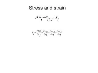
2. STRESS – STRAIN CURVE STRESS – STRAIN CURVE: The mechanical behavior of plastics is defined by using the stress-strain curve obtained in different modes like tension, flexure, compression or shear. The curves obtained in different loading conditions broadly resemble each other. Typical stress and strain curve of plastics obtained intension for constant rate of loading is given below in figure 1. E break Stress ↓ B Strain → A typical stress strain curve D yield C A
Thedeformation behavior is summarized in different stages as discussed below: i)Polymer molecules rest in random fashion in the slid state (A) whereas on initial application of stress at a constant rate, bending and stretching of interatomic bonds takes place (A-B). This results in smaller deformation at molecular level. On relieving the stress, this deformation is recoverable instantaneously. ii)The stretching of molecules continues from B to C, where in C is ‘proportionality limit’ as stress is proportional to strain from A to C (Hooke’s law) on relieving the stress, this anywhere up to the point C deformation is recoverable. This region is known as elastic behavior of polymer materials. The ratio of stress to strain from A to C gives the value of Young’s modulus or modulus of elasticity, which indicates the material’s stiffness. iii)The straightening of molecules continues from C to D but without their slippage. The molecular deformations in this region are recoverable but not instantaneously. Point D in the curve is the Yield Point. As material stretches, its dimensions orthogonal to the axis of applied force decreases, thus the cross-section area decreases. The material thus starts necking.
iv)The deformation from D to E takes place without increase in stress. Strain hardening starts from point E. This hardening of material is a necessary prerequisite for cold drawing phenomena of material deformation when the rate of deformation is constant. Molecules slippage and orientation in the direction of applied stress continuous in E-F region. The deformation of this nature determines the viscous behavior of the material and is irrecoverable. At point F the material fails to withstand the applied stress and breaks. v)These three types of deformation do not occur separately but are superimposed on each other. The bonding & the stretching of the interactive bonds are almost instantaneous. The molecular uncoiling is relatively slow. vi)Area under curve i.e. A to E known as toughness of the material. Modulus of elasticity indicates the stiffness of the material.
The polymers are broadly classified as per their strain behavior, which is the indication of softness, brittleness, hardness and toughness. A hard & strong material has high modulus, high yield stress, usually high ultimate strength & low elongation e.g. acetal. A hard & tough material characterized by high modulus, high yield stress, high elongation at break & high ultimate strength Polycarbonate is considered hard & tough material.
Maxwell Model Ratio of stress to corresponding strain with in the range of greatest stress that the Maxwell is capable to sustaining with any deviation of proportionality of stress to strain. The initial portion of the stress-strain curve between curve point A to C is linear and it follows Hook’s law, which states that the stress is proportional to the strain. The point at which the actual curve dewaks from the straight line is called the Proportional limit, meaning that only upto this point is stress proportional to strain. The behavior of the plastics material below the proportional limit is elastic in nature and therefore the deformations are recoverable.
3. 1 TENSILE PROPERTIES 3.1.1 INTRODUCTION The study of stress in relation to strain in tension depicts the tensile properties of the material. The tensile elongation and modulus measurements are the most important indications of strength in a material and are the most widely specified properties of plastics material. The tensile properties is measurement of the ability of material to with stand forces that tend to pull it apart and to determine to what extent material stretches before breaking. Tensile modulus, an indication of the relative stiffness of a material, which is calculated from a stress-strain curve. Plastics materials are compared on the basis of tensile strength, elongation and tensile modulus data. These data are useful for the propose of engineering design and understanding the characteristics of materials. The properties of material changes by various factors like rate of straining, environmental conditions, the addition of additives like fillers, Plasticizer etc.
3.1.2 DEFINITION 3.1.2 (a) Tensile strength. The maximum Tensile stress ( nominal) sustained by a test piece during a tension test or Ultimate strength of a material subjected to tensile loading otherwise, it is a measurement of the ability of a material to withstand forces that to pull it apart and to determine to what extent the material stretches before breaking. 3.1.2 (b) Tensile Modulus The ratio of tensile stress to corresponding strain at the maximum load. It is an indication of the relative stiffness of a material. 3.1.2(c) Percentage of Elongation at Yield The percentage elongation produced in the gauge length of the test piece at the yield tensile stress. 3.1.2(d) Percentage of Elongation at Break The elongation at break, or at maximum load, produced in the gauge length of the test piece, expressed as a percentage of the gauge length.
UNITS: • Tensile strength / Modulus = Kgf/cm2 • Percentage of Elongation = % • 3.1.3 SIGNIFICANCE: • (1) This test method is designed to produce tensile property data for the control and specification of plastics materials. These data are also useful for qualitative characterization purpose and for research and development. . • (2)Tensile properties may provide useful data for plastics engineering design purposes. However, because of the high degree of sensitivity exhibited by many plastics to rate at straining and environmental conditions.
3.1.4 TEST METHOD: • A)Standard Test Method for Tensile Properties of Plastics (ASTM D 638), • IS-8453, JIS-7113, ISO-1184, BS-2782 • 3.1.5 TEST SPECIMEN: - “Dumb-bell shaped”
3.1.5(a) Dimensions of Test Specimen: Test specimen dimensions vary considerably depending upon the requirements and also various types of materials used. Tensile test piece ISO / DIS 527 Type 1(Broad-waisted Dumb-bell) T= 1min, =10 max, =4preferred, = 4for molded test pieces (Dimension in millimeters)
Tensile test piece ISO / DIS 527 Type 2 (Narrow-waisted Dumb-bell) T= 1 min, =3 max, =2 preferred (Dimension in millimeters)
Tensile test piece ISO / DIS 527 Type 3(Dug-Bone Dumb-bell) (Dimension in millimeters)
3.1.5 (b) Specimen Preparation Methods: • Film - cutting punch & punching machine. • Sheet - contour cutting machine. • Foam - cutting& punching machine. • Liquid - coating & casting process • Thermoset – Compression molding machine, Injection molding machine, Transfer molding machine. • Thermoplastic - Compression molding machine, Injection molding machine. • 3.1.5 (c) CONDITIONING OF TEST SPECIMENS: • Condition the test specimens at 23 ± 2°C and 50 ± 5% or 27 ± 2°C and 65 ± 5% relative humidity for not less than 40 hours prior to test in accordance with procedure as per ASTM D 618. • 3.1.5(d) TEST ATMOSPHERE: • Conduct tests in the standard laboratory atmosphere of 23 ± 2°C and 50 ± 5% relative humidity unless otherwise specified in the test methods. In cases of disagreements, the tolerances are ± 1°C and ± 2% relative humidity.
3.1.6 EQUIPMENT/ INSTRUMENTS DETAILS: • (1)Testing machine consists of • (a)Fixed member • (b)Movable member • (c)Grips • (d)Drive mechanism • (e)Load indicator • (2)Extension Indicator • (a)Modulus of elasticity measurements • (b)Low extension measurements • (c)High extension measurements • (d)Micrometers
3.1.6 (a) EQUIPMENT: The tensile testing machine is a device for applying force onto the test specimen coupled to means of measuring the force and extension. The tensile machine of a constant rate of crosshead movement is used. It has a fixed or stationary member carrying one grip, and a movable member carrying a second grip with variable speed control is employed for the testing. The grips for holding the test specimen between the fixed and movable member should be self aligning and move freely, so that the long axis of the text specimen will coincide with the direction of the applied pull through the center line of the grip assembly. Universal testing machine for testing of the specimen in either Tension or compression
Universal testing machine for testing of the specimen in either Tension or compression
3.1.6 (b) GRIPS: • Different types of grips used for tensile testing are given below. • ·Wedge action type grip - It is suitable for rigid flat sheeting. Wedge action grips
Grip for molded thermoset - It is suitable for thermoset materials. Gribs for molded parts
Vice Type Chucks Grip – It is suitable for thin brittle films. Vice Type Chucks ·Strip Chucks Grip – It is suitable for vary strong laminates and sheet materials. ·Self Tightening Jaws Grip- It is suitable for soft rubber and plastics sheeting for example Plasticised PVC.
3.1.6(c) FORCE MEASUREMENTS: Force measurement in tensile testing machine is carried out with the help of load cells of variable range like 1-1000KN.There are a number of ways in which load cells are constructed with many variations on the basic themes. Two common methods are proof ring and Strain Gauge Bridge. A proof ring depends on the measurement of an extremely small deformation of a stiff but perfectly elastic metal member by a suitable electrical transducer. A strain gauge bridge consists of four resistive elements, three of which are fixed resistors of high stability and the fourth is the measuring element, which is rigidly mounted on a plate in the load cell body such that as the force is applied and the load cell deforms, it distorts the measuring elements. Proof Ring
Strain Gauge 3.1.6(d) ELONGATION MEASUREMENTS: The requirement for measuring elongation in highly extensible materials gives various grades of extensometer with differing degree of precision. The accuracy requirement range from ± 1mm down to ± 0.05mm. These are two types one is Contact & Non contact type. The contact types rely on the physical contact between extensometer and the specimen to sense the change in length during test. Non contact extensometer light being are used to track the movement of contrasting color gauge marks on the test piece, servomechanisms is used to drive the optical heads in the appropriate direction.
3.1.7 TEST PROCEDURE: ·Accurate measurement of width and thickness of the test specimen in the narrow parallel portion at several places to the nearest 0.025mm. The gauge length on the specimen is marked appropriately according to the according to the test standard. ·Fixing the specimen between the grips of the machine while maintaining the alignment. ·The suitable extensometer is attached to measure extension. ·Selection of the lowest test speed that is produced rupture in ½ to 5 min. the speed is the relative rate of motion of the grips during the test. Speed of testing 5± 25%, 50±10% & 500±10% for rigid and semi Rigid material where as 50±10% & 500±10% for non-rigid materials. Speed of testing is calculated from the required initial strain rate. The rate of grip separation is determined from the initial strain rates as follows. A = BC A= Rate of grip separation, mm/min. B= Initial distance between grips (in case of film/sheet) or gauge length (in case of dumbbells) C= Initial strain rate, mm/mm. min.
·Speed is selected according to recorder response and resolution in order to determine modulus. ·The load – extension curve is recorded. ·Using the load value at any point on the load-extension curve tensile strength is calculated by dividing the cross – sectional area. In case of tensile strength at yield and at break, corresponding load values are used from curve for the calculation. ·The elongation of the specimen as dumbbells is measured with reference to the deformation/extension between the gauge marks. Elongation at break and at yield is calculated by using the corresponding length of test specimen at that point . ·The tensile modulus is calculated by using strain values derived from the curve at the maximum stress value.
3.1.9 FORMULA AND CALCULATIONS: Force (load) (N) (1)Tensile strength = Cross-section area of the specimen (mm²) Maximum load recorded (N) (2)Tensile strength at yield (N/mm²) = Cross section area (mm²) Load recorded at break (N) (3)Tensile strength at break (N/mm²) = Cross section area (mm²)
Difference in stress (4)Tensile Modulus = Difference in corresponding strain Change in length (elongation) (5)Elongation at yield, Strain (ε) = Original length (gauge length) (6)Percent Elongation = ε x 100 If the specimen gives a yield load that is larger than the load at break, calculate “percent elongation at yield” otherwise; calculate “percent elongation at break”.
3.1.10 FACTORS INFLUENCING: a) Temperature and Humidity –Recommended Temperature and Humidity is 23oC and 55 –65 %. Tensile Strength decreases as Temperature increases.Moisture works as plasticizer, so it causes then decrease in Tensile Strength and increase the Elongation. Environmental test chamber to study tensile properties at different temperature
b) Test Speed – 0.05 mm/min. to 500mm/min. Elongation is high when Test Speed is minimum i.e. 0.05 mm/min and is lower when Test Speed is maximum i.e. 500 mm/min. c) Method of specimen Preparation – Molecular Orientation has a significant effect on tensile Strength values. A load-applied parallel to the direction of molecular orientation may yield higher value than the load applied perpendicular to the orientation. The opposite is true for elongation. d) Effect of Plasticizer and filler – Soften the material, brings down the Tensile Strength and increase Elongation. e) Crystallinity – With the increase of Crystallinity, Tensile Strength increases. f) Rate of Straining- As the strain rate increases, Tensile Strength and modulus increases. Elongation is inversely proportional to the strain rate.
g) Molecular Weight and Molecular Weight Distribution – With increase in molecular weight, Tensile Strength also increases. Smaller molecules in polymer work as plasticizer. So with increase of Molecular Weight Distribution, Elongation decrease and Tensile Strength increases. The effect of fiberglass orientation
3.1.11. TEST RESULTS: • The report shall include the following: • a)Speed of testing • b)Tensile strength at yield or break, average value, and standard deviation, • c)Tensile stress at yield or break if applicable, average value, and standard deviation, • d)Percent elongation at yield • e)Modulus of elasticity average • 3.1.12 SAFETY PRECAUTIONS: • 1.Specimen is fix in grips proper tightly. • 2.Observation should read carefully. • 3.Specimen is clamped vertically • 4.Before test, test specimen is checked properly for any moulding or machining defects
3.1.14 REFERENCES: ASTM Standards D 229 methods of testing rigid sheet and plate materials used for electrical insulation D 618 methods of conditioning plastics and electrical insulating materials D 638 test method for tensile properties of plastics D 651 test method for tensile strength of molded electrical insulating materials D 882 test methods for tensile properties of thin plastic sheeting D 883 definition of terms relating to plastics D 3039 test methods for tensile properties of fiber resin composites D 4066 specification for nylon injection and extrusion materials.
3.2 FLEXURAL PROPERTIES 3.2.1 INTRODUCTION: These test methods cover the determination of flexural properties of unreinforced and reinforced plastics, including high-modulus composites and electrical insulating material in the form of rectangular bars molded directly or cut from sheets, plates, or molded shapes. These test methods are generally applicable to rigid and semi-rigid materials. However, flexible strength cannot be determined for those materials that do not break or that do not fail in the outer fiber. Two test methods are describes are as follows: (i)Test method 1: A three point leading system utilizing central leading on a simply Supported beam (ii)Test method 2: A four point leading system utilizing two load equally spaced from their adjacent support points with a distance between load points of either 1/3 or 1/2 of the support span.
3.2.2 DEFINITION: 3.2.2(a) Flexural Strength Flexural strength is the ability of the material to withstand bending forces applied perpendicular to its longitudinal axis. The stresses induced due to the flexural load are a combination of compressive and tensile stresses. 3.2.2(b) Flexural Modulus Within the elastic limit, the ratio of the applied stress on a test specimen in flexure to the corresponding strain in the outermost fiber of the specimen. Flexural modulus is the measure of relative stiffness. Unit-Kg/cm2
3.2.3 SIGNIFICANCE: 1.Flexural properties determined by test method ‘1’ are especially useful for quality Control and specification purposes. 2.Materials do not fail at the points of maximum stress under test method ‘1’ is test by test method ‘2’. Flexural properties are determined by second method, are also useful for quality control and specification purposes. The basic difference between the two types of method is the location of maximum bending moment and maximum axial fiber stress.
3.2.4 TEST METHOD: • Flexural properties of unreinforced & reinforced plastics & Electrical Insulating materials (ASTM-D-790), JIS-7203-1982, BS-2782. • 3.2.5 TEST SPECIMEN • 3.2.5 (a) Specimen Preparation Method • The specimen uses for flexural testing are bars of rectangular cross sections and are cut from sheets, plates or molded shapes. The common practice is to mold the specimens to the desired finished dimensions.
3.2.5 (b) Dimensions of Test Specimen The specimens of size 1/8 x ½ x 4 in. are the most commonly used.
3.2.6 EQUIPMENT DETAILS: (i)Testing machine: A properly calibrated testing machine that is operated at constant rate of cross- head motion over the range indicated and in which the error in the load measuring system shall not exceed ± 1% of maximum load expected to the measured. (ii)Noses & supports: The loading noses and supports shall have cylindrical surfaces in order to avoid excessive indentation, or failure due to stress conc. Directly under the loading noses, the radius of noses and supports are atleast 3mm for all specimens.
3.2.7 TEST PROCEDURE: ØKeep the rectangular specimen horizontally in the stationary crosshead surface. ØThe movable portion having the bending nose ØThe test is initiated by applying the load to the specimen at the specified crosshead rate. ØThe deflection is measured either by a gauge under the specimen in contact with it in the center of the support span or by measurement of the motion of the loading nose relative to the supports. ØThere are two test methods to conduct the test,
3.2.7(a) Method I: It is a three-point loading system utilizing center loading on a simple supported beam. A bar of rectangular cross section rest on two supports & is loaded by means of a loading nose midway between the support the maximum axial fiber stresses occur on a line under loading nose. Force involved in bending a simple beam
3.2.7(b) Method II: It is four -point loading system utilizing two load points equally spaced from their adjacent supports point, with a distance between load points of one-third of the support span. In this method, the test bar rests on two supports & is loaded at two point (by means of two loading noses), each on equal distance from the adjacent support point. This method is very useful in testing materials that do not fail at the point of maximum stress under a three-point loading system the maximum axial fiber stress occurs over the area between the loading noses. Schematic of specimen arrangement for flexural testing
3.2.9 FORMULA AND CALCULATION: 1)Calculate the rate of cross-head motion as follows and set the machine for the calculated rate, or as near as possible to it, R = Z l2 / 6d Where, R = rate of cross-head motion (mm/min) l = support span (mm) d = depth of beam (mm) Z = rate of straining of entire fiber (mm/min) 2) Terminate the test in the maximum strain in the outer fiber has reached 0.05 mm/min. The deflection at which distortion occurs are calculated by ‘r’ equal to 0.05 mm/min as follows D= rl2 / 6d Where, D = midspan deflection (mm) r = strain (mm/mm) l = support span d = depth of beam (mm)
3)Max.fiber stress- test method ‘1’ S = 3PL / 2 bd2 Where, S = stress in the outer fiber at midspan (Mpa) p = load at given point on the load deflection curve(v) L= support beam (mm) b= width of beam tested (mm) d = depth of beam tested in (mm) 4)Maximum fiber stress for beam tested at large support spans-test method ‘1’, S = (3PL / 2 bd2 ) 1+ 6(D/L)2 – 4(d/l) (D/L) 5)Max.fiber stress-test method ‘2’ S = PL / bd2 For a load span of ½ of the support span S = 3PL / 4 bd2
6)Maximum fiber stress test method ‘2’ for beam tested at large support span:- S = (PL / bd2 ) 1 + (4.70 D2 / L2 – (7.04 Dd / L2 )] For a span of one-half of the support Span: S = (3PL / 4bd2 ) * [ 1- (10.91 Dd / L2 ) ]