Download
1 / 13
130 likes | 304 Views
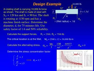
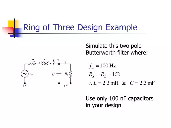
Ring of Three Design Example. Simulate this two pole Butterworth filter where:. Use only 100 nF capacitors in your design. Design 1. Both capacitors must be 100 nF:. Design 2. 23 k W. 23 k W. 23 k W. 100 nF. Design Example 2. Simulate this two pole Butterworth filter where:.

E N D
Ring of Three Design Example Simulate this two pole Butterworth filter where: Use only 100 nF capacitors in your design
Design 1 Both capacitors must be 100 nF:
Design 2 23 kW 23 kW 23 kW 100 nF
Design Example 2 Simulate this two pole Butterworth filter where: Again, use only 100 nF capacitors in your design
Design 2 Both capacitors must be 100 nF:
Leapfrog Filters • By continuing the concepts of operational simulation, higher order filters can be built • Each inductor requires an inverting integrator (1 op-amp), each capacitor requires a non-inverting integrator (2 op-amps) • Op-amps required = 3N/2 • Complex circuits can be simulated using similar principles • Scale factors for all variables can be adjusted arbitrarily • By doing this, the output voltage range for each op-amp can be adjusted to maximise the dynamic range of the filter
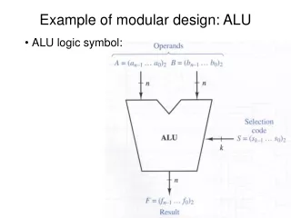
Comparison of Active Filter Designs • Synthesis by Sections • Low op-amp count – N/2 • Noise/output voltage range trade off • Sallen & Key sensitivity • Component Simulation • Robust despite component tolerances • Higher op-amp count – N • Easier to realise transmission zeros • Dynamic range limitation • Operational Synthesis • Robust again • Even higher op-amp count – 3N/2 • Op-amp output ranges can be individually optimised.
Revision • What should you be expected to do in a typical exam question ? • Understanding of basic principles. • Ability to perform simple circuit analysis and/or design. • Applying skills to unfamiliar problems.
Power Amplifiers • Basic Principles • Operating modes of amplifiers • Power dissipation and thermal effects • Design/Analysis • Class A, B, AB amplifiers • Use of multiple transistor units (Darlington) • Associated circuits (current mirror, VBE multiplier)
Low Noise Amplifiers • Basic Principles • Noise figure and noise temperature definitions • Sources of noise • Equivalent circuits • Design/Analysis • Noise figure of a common-emitter amplifier
High Frequency Amplifiers • Basic Principles • Frequency response calculations • Internal junction capacitances of a BJT • The Miller effect • Design/Analysis • Frequency responses of • A common-emitter amplifier • A cascode amplifier
Active Filters • Basic Principles • Types of filter and differences between them • Transfer functions, poles and zeros • Design/Analysis • Synthesis by sections, first and second order Sallen and Key sections • Component simulation for • Grounded inductors • Floating inductors • Grounded FDNRs • Operational Simulation: Ring of Three