Download
1 / 29
290 likes | 426 Views
Modeling and Optimization of Vehicle Drivetrain Dynamic Performance Considering Uncertainty. Zissimos P. Mourelatos, Associate Prof. Daniel N. Wehrwein, Graduate Student Mechanical Engineering Department Oakland University. Purpose of study Dynamic Vehicle Model Bond Graph Modeling

E N D
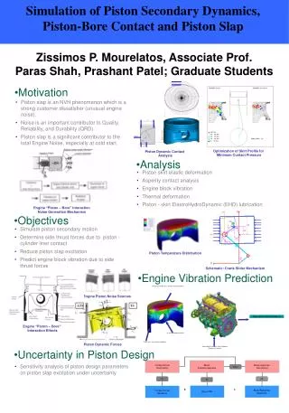
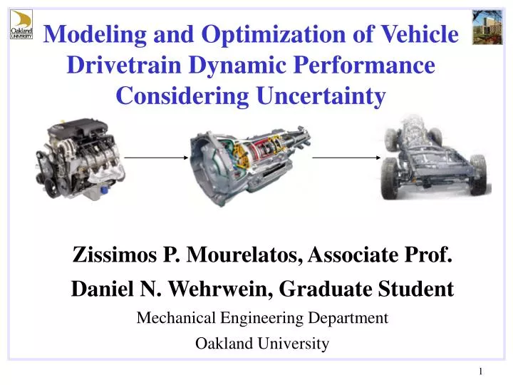
Modeling and Optimization of Vehicle Drivetrain Dynamic Performance Considering Uncertainty Zissimos P. Mourelatos, Associate Prof. Daniel N. Wehrwein, Graduate Student Mechanical Engineering Department Oakland University
Purpose of study • Dynamic Vehicle Model • Bond Graph Modeling • Optimization Process • Deterministic Optimization • Probabilistic Optimization (RBDO) • Summary and Conclusions Outline
Optimize drivetrain performance under uncertainty • Transmission Gear Ratios • Final Drive Ratio (axle ratio) • Transmission Shift Points • Acceleration Performance • Fuel Economy • Trailer Towing Acceleration and Gradability Purpose of Study Design Variables Performance Measures
Graphical method for system modeling Energy based and multidisciplinary Modular; components can be modeled separately and assembled Bond graphs and block diagrams are interchangeable. Simulink can be used Bond Graph Modeling
Engine is modeled as a rigid body with friction Torque input is a look up table of engine speed and throttle position and is based off a steady state torque map Engine Model Bond Graph Block Diagram
Torque Converter Model • A complete model would require complex CDF modeling • Dynamometer data is used instead to model torque ratio and converter efficiency
GM 4L60E, four speed automatic Two planetary gear sets in series Clutch actuation determines gear state Ratio of sun and ring gear on each planetary gear set determines transmission ratios Transmission Description
Planetary gear sets, clutches, and a controller to actuate each clutch are modeled Each planetary gear set has a sun, a ring, and a planetary gear Each clutch is actuated through a controller using a shift table. Transmission Model Shift Table Planetary Gear Set
Two inertia elements connected by a spring model each shaft Tire is assumed to be in constant contact with the road The tire is modeled as a lump inertia with a discrete spring between the tire and the road The vehicle is modeled as a rigid body with standard rolling resistance and aerodynamic drag Driveline and Vehicle Model 2WD Driveline
Common performance targets for full size trucks: Acceleration Performance Gradeability Trailer Towing Performance Fuel Economy Cost, weight, and packaging (not used) Vehicle Performance Targets
Optimization design variables : Transmission planetary ratios Axle ratio Transmission shift points Ratios of integers Depend on ratios Drivetrain Optimization Process
In order to avoid integer programming, the optimization is done in two stages: Optimize axle and transmission ratios for maximum highway fuel economy Optimize transmission shift points for minimum 0 to 90 acceleration time Drivetrain Optimization Process (cont.)
Output Output Input Input Simulink Simulation Simulink Simulation Design Design Drivetrain Optimization Process (Cont.) Gear Ratio Optimization Stage 1 Transmission Shift Point Optimization Stage 2
Deterministic Optimization of Axle and Transmission Ratios Fuel Economy Trans ratios Axle ratio
Deterministic Optimization of WOT Transmission Shift Points 0 to 90 time shift points
Propagation Output Input Analysis / Simulation Design Quantification Uncertainty (Quantified) Uncertainty (Calculated) 2. Propagation 3. Design (RBDO) Design Under Uncertainty
Feasible Region Reliable Optimum Design Under Uncertainty (RBDO) x1 g1(x1,x2)=0 g2(x1,x2)=0 Increased Performance f(x1,x2) contours x2
Gear ratios are ratios of integers. • Transmission shift points are not sensitive to small errors in vehicle speed and throttle position. Deterministic Uncertainty in Our Model • Viscous friction at the transmission, ring gear, and pinion gear • The engine output torque
Probabilistic Optimization of Axle and Transmission Ratios Deterministic design variables Probabilistic design parameters Engine torque multiplier Viscous friction coef.
Summary & Conclusions • A vehicle drivetrain dynamic model is developed using bond graphs. • Transmission ratios, axle ratio, and WOT shift points were optimized using a two-step optimization process. • Both deterministic and probabilistic optimization was performed. • Highway fuel economy was improved by 11% • 0 to 90 time was improved by 3.9% • 0 to 60 time was improved by 4.5%