Download
1 / 20
200 likes | 348 Views
ATLAS Pixel Readout Driver Electronics Lawrence Berkeley National Labs Presented by Sriram Sivasubramaniyan. BOC to ROD Mapping. B-Layer: Six to Seven modules per ROD at 160Mbit/module, or 24-28 40Mbit equivalent data streams.

E N D
ATLAS Pixel Readout Driver Electronics Lawrence Berkeley National Labs Presented by Sriram Sivasubramaniyan
BOC to ROD Mapping • B-Layer: Six to Seven modules per ROD at 160Mbit/module, or 24-28 40Mbit equivalent data streams. • Layer1: 13 modules per ROD at 80Mbit/module, or 26 40Mbit equivalent data streams. • Layer2: 26 modules per ROD at 40Mbit/module, or 26 40Mbit data streams. • Disks: 24 modules per ROD at 40Mbit/module, or 24 40Mbit data streams.
Links to Formatter Mapping • Blayer : Each Formatter FPGA is mapped to Two Pixel B-layer Modules at 160 Mbits/sec equivalent to 4 40 Mbits/Sec Links. • Layer1: Each Formatter FPGA is mapped to Four Pixel Layer1 Modules at 80 Mbits/sec equivalent to 2 40 Mbits/Sec Links. • Layer2: Each Formatter FPGA is mapped to Eight Pixel Layer2 Modules at 40 Mbits/sec. • Disks: Each Formatter FPGA is mapped to Six Pixel Disks Modules at 40 Mbits/sec.
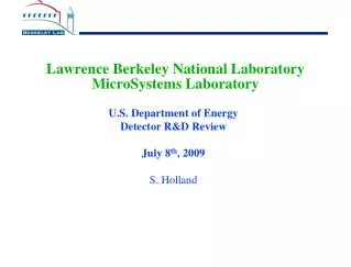
Note: XCV400E-6fg676 NOTE: resolve latency requirement 12+6+1+15 clk cycles Formatter Writes Trailer Encoder: latch Trailers and store new internal state on ShowTrailerFLAGS MasterNSlave 1b Link Formatter And Link OutputFIFOs L1TriggerPulse 1b FormatterWritesTrailer[7..0] 8b StoreTrailerHit 1ea 2 state state machine ClearCurrentFlag D FF FormatterWritesTrailer 8b ShowTrailerFLAGS 1b TOKENin 1b from previous chip Mode Bit Readout 2, 12bit words 2bits each link TOKENout 1b to next chip OverflowError[7..0] 8b TimeOutError[7..0] 8b Rod Controller DataValid[7..0] 8b Link[7..0]DATA 8b Link[7..0]hasTOKEN 8b ModeBitsIN[7..0] 8b HeaderTrailerLimit[7..0] 8b HeaderTrailerLimit[7..0] 8b HeaderTrailerLimit 1b Formatter BUS 21b D[15..0]+ A[3..0]+ RNW RODBusyLimit[7..0] 8b RODBusyLimit[7..0] 8b RODBusyLimit 1b FormatterBUSStrobe[7..0] 8b FifoDATA 32b FifoDATA 32b RegTransferACK[7..0] 8b HOLDoutput 1b HOLDoutput 1b StrobeModeFifos 1b StrobeModeFifos 1b LimitREGs 29b ModeFifoEmpty[7..0] 8b ModeFifoEmpty 1b OverflowError[7..0] 8b OverflowError 1b TimeOutError[7..0] 8b TimeOutError 1b Event Fragment Builder DataValid[7..0] 8b DataValid 1b Link[7..0]hasTOKEN 8b Link Number: 8:4 Encoder Link# hasTOKEN 4b RegTransferACK[7..0] 8b ThisChipHasToken 1b Operations Controller: FormatterBUSStrobe[7..0] 8b HeaderTrailerLimitREG 8b A[7..4] 4b RodBusyLimitREG 5b FormatterBUS 26b from RodContoller Strobe 1b TokenToReadOutTimeOutREG 7b Acknowldge 1b DataOverflowLimitREG 9b NOTE: RodBusyLimitREG are the 5b high order bits of the occupancy count. So the busy limit is modulo 8 - Please advise!
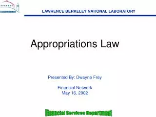
PIXEL DECODER STATE MACHINE STATE DIAGRAM Reset State: Trailer Clear bit_count Clear bit_count State: Reset Write trailer Clear serial_data_in If trailer_detect = ‘1’ Clear trailer_counter Set normal_not_raw to 0 State: Idle State: Raw_data Set Bit_count to new value Clear bit_count Set normal_not_raw to 1 Write Raw_data If header is detected If sync_bit not detected State: L1-ID If Sync-bit not detected Clear bit_count If sync-bit not detected If sync-bit not detected Write L1_ID If trailer_detect=‘1’ If sync-bit not detected If sync-bit not detected Set Bit_count to new value State: FE_FLAG If sync bit detected Set Bit_count to new value Write FE_FLAG State: BC-ID Set Bit_count to new value State: MCC_FLAG New_hit_address Write BC_ID State: FE_ID Write MCC_flag Write FE_ID Set bit count to new value If error set bit count to new value State: Hit If FEID New_hit_data If hit Write hit data If trailer_detect = ‘1’ If sync bit not detected If error If trailer is detected
PIXEL DECODER LOGIC • Header Search :Searches for 11101 , allowing 1 bit error. • Decodes Serial data stream , sensitive to : * Hits : Packs 1 hit per word, with TOT. * FE and MCC flagged Errors:Flagged and passed downstream. * Sync Bit Errors:Flagged, Passed downstream, go to write raw data mode until trailer arrives. • Trailer Search: No bit Errors allowed. • Reset of ROD masks off the decoder inputs. • Header Mode when input buffers near full. • Decoder operates at 40 Mhz clock. • Mask bit input to disable the decoder.
When the Header is detected the next data expected by the detector is L1-ID. • If the L1_ID is detected then the next expected data is BC_ID. • If the BC_ID is detected the next data can be either MCC_FLAG or the FE_ID. • After the MCC_FLAG has been detected the next data expected is FE_ID. • The Data Expected after FE_ID is either Front end Error Flag or the Hit data. In the absence of any error the data is hit data.
There is a possibility of Multiple hits in the same FE_ID therefore the data expected after the hit is either a hit data or a trailer or a new FE_ID or even a FE_FLAG. • There is also a possibility of new FE_ID after the Front End error Flag is detected. • If the Sync bit is not detected then the Decoder does not recognize the data & outputs the data as Raw data until a trailer is detected. • Once the trailer is detected & written to the output the decoder asserts decoder_writes_trailer high . • Whenever the decoder writes the data to the output formatter_writes_word goes high.
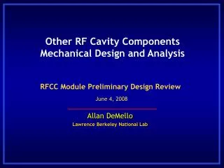
Link Formatter Block Diagram (Layer1) Normal_n_Raw _out 1b Header_detect_ i 1b Process to detect header Link_in 2 b Normal_n_Raw_i 1b Link_in_i Finite state Machine for next states New_hit_data_i 1b Trailer_detect_i 1b New_hit_location_i 1b Rst_in 1b Header_sh_reg 6b serial_link_i Clk_in Data_out 32b Enable_in 1b Raw_data_odd_i Finite state Machine for writing output Almost_full_ flag_i Raw_data_even_i Almost_full_in Process to detect trailer Serial_data_reg 28b Fe_reg 4b
Link Formatter Block Diagram ( Blayer) Normal_n_Raw _out 1b Process to detect header Link_in 4 b Normal_n_Raw_i 1b Header_detect_ i 1b Link_in_i Finite state Machine for next states New_hit_data_i 1b Trailer_detect_i 1b New_hit_location_i1b Rst_in 1b serial_link_i Header_sh_reg 12b Clk_in Data_out 32b Raw_data_odd_i Raw_data_even_i Enable_in 1b Finite state Machine for writing output Almost_full_ flag_i Almost_full_in Process to detect trailer Serial_data_reg 32b Fe_reg 4b
Link Formatter Block Diagram (Layer 2 and Disks) Normal_n_Raw _out 1b Link_in 1b Header_detect_ i 1b Process to detect header Normal_n_Raw_i 1b Link_in_i Finite state Machine for next states New_hit_data_i 1b Trailer_detect_i 1b New_hit_location_i 1b Rst_in 1b Header_sh_reg 6b serial_link_i Clk_in Data_out 32b Raw_data_odd_i Raw_data_even_i Enable_in 1b Finite state Machine for writing output Almost_full_ flag_i Almost_full_in Process to detect trailer Serial_data_reg 28b Fe_reg 4b
B-Layer Pixel ROD • Six to Seven Pixel (B-Layer)Modules at 160Mbits/Sec per ROD. This design can accommodate up to 8 Pixel Modules. • Four Formatter FPGAs per ROD. • Two Pixel Modules per Formatter. • Two Formatters For each Event Fragment Builder Engine. • Two EFB engines per EFB FPGA. • One Router per ROD.
Barrel Layer 1 Pixel ROD • Thirteen Pixel (Layer 1) Modules at 80Mbits/Sec per ROD. • Four Formatter FPGAs per ROD. • Four Pixel Layer 1 Modules per Formatter FPGA. • Two Formatters For each Event Fragment Builder Engine. • Two EFB engines per EFB FPGA. • One Router per ROD.
Barrel Layer 2 Pixel ROD • Twenty Six Pixel (Layer 2) Modules at 40Mbits/Sec per ROD. • Four Formatter FPGAs per ROD. • Eight Pixel Layer 2 Modules per Formatter. • Two Formatters For each EFB Engine. • Two EFB engines per EFB FPGA. • One Router per ROD.
Disks Pixel ROD • Twenty Four Pixel (Disks) Modules at 40Mbits/Sec per ROD. • Four Formatter FPGAs per ROD. • Six Pixel Layer 2 Modules per Formatter FPGA. • Two Formatters For each Event Fragment Builder Engine. • Two EFB engines per EFB FPGA. • One Router per ROD.
Pixel ROD Simulation • The VHDL Codes were Synthesized and the back annotated codes were Simulated. • Test Files generated for each stage by ‘C’ Programs were used to simulate the various Modules. • The Formatter, Event Fragment Builder, Router were simulated using the test vectors.
Pixel ROD Simulation • Formatter Simulation • Four Events generated by the C simulation, running synchronously and simultaneously to each Formatter FPGAs. • Event Fragment Builder Simulation. • The Event Fragment Builder was simulated with both the test Vectors generated from ‘C’ Simulation as well as the outputs from the Formatters. • The outputs of the Four B-layer Formatters were tied to the inputs of the Event Fragment Builder and simulated.
Pixel ROD Simulation • The Event Fragment Builder outputs matched the expected outputs. • Router Simulation. • The Router was simulated with test vectors generated from C simulation. • Logic level simulation and back-annotated code simulation was performed. • Currently working on Router Simulation by tying up the Router inputs to the Event Fragment Builder FIFO outputs.
Pixel ROD Status • Formatter VHDL code written and debugged for all the Pixel ROD versions. • Necessary Modifications were made in the EFB and Router VHDL Code. • Logic Level and Back-annotated code Simulation Complete. • Pixel ROD Testing Hardware testing should commenced soon.