Download

1 / 24
240 likes | 374 Views
SID Assembly Procedures. European and Japanes Site. Marco Oriunno , SLAC SID Workshop - August 22, 2012. Assembly procedures driven by SID design features. Compact design with 5 T Solenoid Single Ring Barrel ~ 4’000 tons Self Shielded: Stray Fields & Radiation

E N D
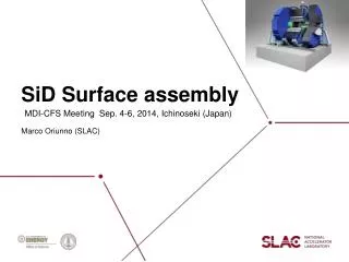
SID Assembly Procedures • European and Japanes Site Marco Oriunno , SLAC SID Workshop - August 22, 2012
Assembly procedures driven by SID design features Compact design with 5 T Solenoid Single Ring Barrel ~ 4’000 tons Self Shielded: Stray Fields & Radiation Short L* with QD0’s supported from the doors
Assembly Procedures for different Sites • The assembly procedure will be different for the two sites • Both layouts must satisfy push-pull requirements • The detector hall must be optimized for costs: benefits vs. features • Vertical shafts (Europe, Americas) • Horizontal shafts (Japan)
Detector Hall Design: Vertical Shaft • Five shafts Layout : single large shaft above the IP, two smaller shafts on the alcoves, two shafts for personnel access. • Cost optimization vs. features, like IP commissioning without detectors.
Surface assembly a la CMS 200 + 20 tons Crane 4’000 tons Gantry • Assembly of Iron Doors+Barrel on surface • Commissioning of the magnet on surface • Very Large capacity gantry
Detector Hall, Japanese Mountain Site e+ To the Surface ILD X IP SID To Damping Ring e- Installation tunnel
Site Delivery prior the start of the Detector Assembly • Two Cranes 215 tons, • Platforms • Minimum set of infrastructures (Power, Compr. Air, etc.) • Pacmen can wait until detectors are ready
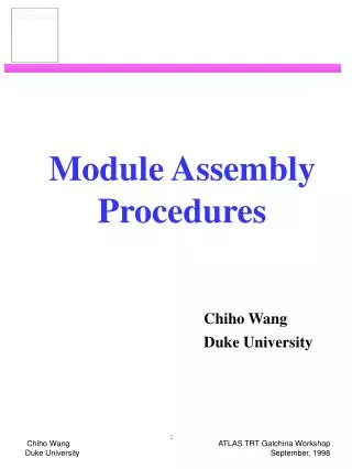
Door Assembly Pacman on the door HCAL& EMCAL FWR 11 x 200mm Iron plates 40mm gap Total Mass ~ 2’300 Tons
Door Design Intra-plate connections Spacer Offset
Door Assembly on the platform 66 Tons • 11 trips from the Surface (per Door) • 1 heavy lift / day
Iron Barrel Yoke layout • Bolted assembly, 144 plates 200 mm thick, 40mm gap • Opportunity to make blank assembly at the factory before shipping • Preliminary Contacts with Kawasaki Heavy Industries • Plate thickness tolerance for each: 0.1mm • Plate flatness: 4mm (in a plate) • Fabrication (assembling & welding) tolerance: 2mm • Full trial assembly: capable (but need to study) 3990 tons Max. Crane capacity 215 Tons
Barrel Assembly • 16 trips from Surface • 1 heavy lift / day
Solenoid assembly Ring 2 • Assembly on Site (surface) • Test with low current Ring 1 DID Total Mass = 180 Tons Solenoid Cross section
Solenoid Installation 215 tons Crane
HCAL Barrel Assembly Assembly beam Assembly Spider Insertion beam Truck with HCAL Module SLD, Liquid Argon Calorimeter Assembly Beam (Option 1) CMS HCAL barrel on the cradle (Option 2)
Cryogenic Layout : Two options • Plan A : Cold Boxes are stationary. Cold Transfer lines to each detector. Reliability for push-pull. Not off-the-shelf. • Plan B : Cold Boxes on the platform. Warm Transfer lines to each cold box. Vibrations, fringe field effects, space
Integration of the Cryogenic plant on the platform • Main LHe refrigerator and LHe2 for the QD0’s above level on metallic structure. Valve Box LHe2 LHe Box LHe2
Compressor cavern • The compressor cavern for the Gas Helium is located at ~300 m form the detector hall
Flexible Line to the Compressor • The GHe line from the compressor is flexible, in a cable chain Cable Chain Gas line 28 m
Flexible Line to the Compressor • The GHe line from the compressor is flexible, in a cable chain Gas line Cable Chain 28 m
Cryogenic layout: SID and ILD • The GHe line from the compressor is flexible, in a cable chain
Summary • We developed credible Assembly scenarios for both the Vertical and Horizontal access shafts. • The Japanese Mountain site with horizontal shafts is preferred by SID, being closer to the original assembly procedure considered for the design of the detector. • Still a margin to optimize further costs and procedures. • More work is needed to define the layout of the cryogenic distribution and services • The logistic and procedures of the Portal Site on surface for the preassembly of the detector need to be defined.