Download
1 / 40
400 likes | 522 Views
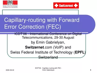
Path Diversity with Forward Error Correction (PDF) System for Packet Switched Networks. Thinh Nguyen, Avideh Zakhor. INFOCOM 2003. Twenty-Second Annual Joint Conference of the IEEE Computer and Communications Societies. IEEE , Volume: 1 , 30 March-3 April 2003 Pages:663 - 672 vol.1. Agenda.

E N D
Path Diversity with Forward Error Correction (PDF) System for Packet Switched Networks Thinh Nguyen, Avideh Zakhor INFOCOM 2003. Twenty-Second Annual Joint Conference of the IEEE Computer and Communications Societies. IEEE , Volume: 1 , 30 March-3 April 2003 Pages:663 - 672 vol.1
Agenda • Introduction • Motivation • Proposed System • Overview • Architecture • Redundant Path Selection • Simulations • Conclusion & Comments
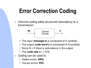
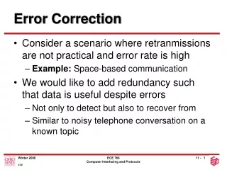
Introduction • Video Streaming is a delay sensitive application • Possible solutions include • Layered video codecs • Error resilient codecs • Forward error correction • TCP-friendly protocol • Edge architecture
Introduction • Most schemes assume a single fixed path between the receiver and the sender throughout the session • If congestion happens along that path, video suffers from high loss rate and jitter. • Previous studies show sub-optimal routing path exists. • Path Diversification System with Forward error correction (PDF) is proposed
Introduction • Recent works and models suggest redundancy path between nodes in the Internet • The Question is whether there exists sufficiently disjoint paths between a pair of senders and receivers on the Internet
Motivation • Number of successive lost packets is smaller in scheme 2. • Scheme 2 transforms the bursty loss into uniform loss • Increase in the FEC efficiency
Motivation - Experiment Receiver Sender A (1 sec, 10ms) Average good time Average bad time (1 sec, 10-50ms) B
Motivation - Experiment • Packets divided equally at 15 packets each • When the average bad time of B increases, more packets are sent on path A. • Multipath can be 15 times higher than unipath • Even the loss rate of path B is five times higher than path A, sending packets simultaneously over two paths still benefits.
System Architecture Overlay Network Relay Node Receiver Sender Router Physical Network
Relay Node A Traceroute Receiver Sender Traceroute Traceroute Traceroute Relay Node B Relay Node C • Sender executes traceroute from itself to all relay nodes and receiver. • Link latencies and router names are obtained. • Sender instructs relay nodes to execute traceroute from themseleves to receiver. • Send the path information back to the sender
System Overview Relay Node A (S, RN_A, 100us) Receiver Sender (S, Rec, 201us) (S, RN_B, 73us) (S, RN_C, 51us) Relay Node B Relay Node C • Sender executes traceroute from itself to all relay nodes and receiver. • Link latencies and router names are obtained. • Sender instructs relay nodes to execute traceroute from themseleves to receiver. • Send the path information back to the sender
Relay Node A Command (traceroute, receiver) Receiver Sender Command (traceroute, receiver) Command (traceroute, receiver) Relay Node B Relay Node C • Sender executes traceroute from itself to all relay nodes and receiver. • Link latencies and router names are obtained. • Sender instructs all relay nodes to execute traceroute from themseleves to receiver. • Send the path information back to the sender
Relay Node A (RN_A, Rec,24us) (RN_A, Rec,24us) Receiver Sender (RN_B, Rec,130us) (RN_C, Rec,95us) (RN_B, Rec,130us) (RN_C, Rec,95us) Relay Node B Relay Node C • Sender executes traceroute from itself to all relay nodes and receiver. • Link latencies and router names are obtained. • Sender instructs all relay nodes to execute traceroute from themseleves to receiver. • Send the path information back to the sender
Relay Node A Receiver Sender Redundant path Relay Node B Default path Relay Node C • The sender, based on the information received , select the redundant path. • Sender sends the setup packet to that selected relay node, containing flow ID, IP address and the port number of the receiver. • The relay node builds up a table for forwarding packets. • Each time, the sender attaches the flow ID in sending packets for relay node to where it should forward to.
Relay Node A Setup Command (flowID, recvIP, recvPort) Receiver Sender Relay Node B Relay Node C • The sender, based on the information received , select the redundant path. • Sender sends the setup packet to that selected relay node, containing flow ID, IP address and the port number of the receiver. • The relay node builds up a table for forwarding packets. • Each time, the sender attaches the flow ID in sending packets for relay node to where it should forward to.
Relay Node A Setup Command (flowID, recvIP, recvPort) Receiver Sender FlowID RecvIP RecvPort …. …. …. …. …. …. flowID recvIP recvPort …. …. …. • The sender, based on the information received , select the redundant path. • Sender sends the setup packet to that selected relay node, containing flow ID, IP address and the port number of the receiver. • The relay node builds up a table for forwarding packets. • Each time, the sender attaches the flow ID in sending packets for relay node to where it should forward to.
Relay Node A Data (flowID, recvIP, recvPort) Receiver Sender FlowID RecvIP RecvPort …. …. …. …. …. …. flowID recvIP recvPort …. …. …. • The sender, based on the information received , select the redundant path. • Sender sends the setup packet to that selected relay node, containing flow ID, IP address and the port number of the receiver. • The relay node builds up a table for forwarding packets. • Each time, the sender attaches the flow ID in sending packets for relay node to where it should forward to.
Redundant Path Selection • Finding optimal path is difficult and complex • Traffic conditions vary rapidly • Use of BGP between ASes. • No. of link along the path and their associated latency can not be obtained. • OSPF, by periodically probing. • Not scalable • Passive Probing tools • Measurement process based on the application sending rates
Redundant Path Selection • However, Finding two path with absolute lowest loss rates for the proposed PDF system may not be needed • Complexity increases, thus not scalable • Other paths may still achieve reasonable performance Performance is still better than uni-path case even one path has five times loss than the other.
Redundant Path Selection Denote a network topology as directed graph G=(V,E) with vertices and edges
Redundant Path Selection Step 1 • Compute a set of relay nodes O’ that result in the minimum number of joint links between the default path and all the redundant paths via a node in O, O’=arg mink p’(u,k,v) ∩ p*(u,v) where , p’(u, k, v) is redundant path via node k p*(u,v) is the default path Redundant path Default path
Redundant Path Selection Step 2 • Choose node k’ that results minimum weight associated with the corresponding redundant path, k’=arg minl w(p’(u, l, v)) where , Redundant path Default path 30us 50us 80us 130us
Redundant Path Selection Procedure repeated for All remaining relay nodes for selecting the new redundant path Advantage Traceroute only invoke at the start of the session. Drawback Information from Traceroute is not complete and accurate Some ASes hide information from their networks
Simulation 1 AS Interconnections Routers Interconnections
Simulation Flat Topology • Randomly choose a set of participating nodes • Randomly choose a pair of sender and receiver among all participating nodes • Default path is set as the smallest latency between the sender and receiver. (calculated by OSPF) • Apply the redundant path selection strategy • Repeat 5000 times
Simulation Flat Topology • Randomly choose a set of participating nodes • Randomly choose a pair of sender and receiver among all participating nodes • Default path is set as the smallest latency between the sender and receiver. (calculated by OSPF) • Apply the redundant path selection strategy • Repeat 5000 times
Simulation Flat Topology • Randomly choose a set of participating nodes • Randomly choose a pair of sender and receiver among all participating nodes • Default path is set as the smallest latency between the sender and receiver. (calculated by OSPF) • Apply the redundant path selection strategy • Repeat 5000 times
Simulation Flat Topology • Randomly choose a set of participating nodes • Randomly choose a pair of sender and receiver among all participating nodes • Default path is set as the smallest latency between the sender and receiver. (calculated by OSPF) • Apply the redundant path selection strategy • Repeat 5000 times
Simulation Flat Topology • Randomly choose a set of participating nodes • Randomly choose a pair of sender and receiver among all participating nodes • Default path is set as the smallest latency between the sender and receiver. (calculated by OSPF) • Apply the redundant path selection strategy • Repeat 5000 times
Simulation Flat Topology • Randomly choose a set of participating nodes • Randomly choose a pair of sender and receiver among all participating nodes • Default path is set as the smallest latency between the sender and receiver. (calculated by OSPF) • Apply the redundant path selection strategy • Repeat 5000 times
Simulation Results Only 2% of total nodes already give less than 10% shared links. HAB 2 has higher degree of connectivity than HAB 1 Flat topology does not contain routing between ASes
Simulation Results The latency decreases as # of participating nodes increase because more choice of redundant paths Initial latency = 1.7 Decrease gradually beyond 20%
Simulation Results (Left) Reduction in latency does not result from fewer links (Right) P(two or fewer shared link) is 100%(F), 90%(ABII), 85%(AB1)
Simulation - NS Default path : 11 links …… Sender Receiver …… Redundant path : 18 links
Parameter • 3 Scenario • Sender streams the video to the receiver at 800kbps on default path only • Sender streams the video to the receiver on both redundant and default path at 400bps for each path with two paths are completely disjoint • Same as case 2, but with one shared link
Results Case 1 Case 2 Case 3
Results Effective loss rate = # of irrecoverable packets / total # of packets Can be 7 times better Even have 3 shared links (out of 11), the performance is still twice better.
Conclusion • Path Diversity Scheme (PDF) • Heuristic scheme for selecting redundant path • Simulations done on Internet-like topologies • NS Simulations for comparing unipath and multipath scheme
Comments • PDF performances highly depends on the shared link. • Q: what is the performace when the percentages of shared link becomes 50%? • Latency incurred in PDF may not be suitable for real time application • Q: Considers the end-user throughput in P2P environment, it most likely exceeds 150ms.