Download
1 / 11
110 likes | 259 Views
Plans for collimator survival and SLAC tests. J. L. Fernandez-Hernando STFC/ASTeC Daresbury Lab. Beam Parameters at SLAC ESA and ILC. *possible, using undamped beam. T480 “wakefield box”. ESA beamline. 1 ± 0.1 V/pC/mm. 1.4 ± 0.3 V/pC/mm. 1 ± 0.2 V/pC/mm. 1.7 ± 0.1 V/pC/mm.

E N D
Plans for collimator survival and SLAC tests J. L. Fernandez-Hernando STFC/ASTeC Daresbury Lab
Beam Parameters at SLAC ESA and ILC *possible, using undamped beam
T480 “wakefield box” ESA beamline
1 ± 0.1 V/pC/mm 1.4 ± 0.3 V/pC/mm 1 ± 0.2 V/pC/mm 1.7 ± 0.1 V/pC/mm 1.9 ± 0.2 V/pC/mm 1.7 ± 0.1 V/pC/mm 2.6 ± 0.1 V/pC/mm
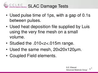
A deviation from normal orbit of 10σx would have these effects on this particular spoiler design made of Be and of 0.05 radiation lengths of flat part. 950MPa, and tensile, which is way above tensile strength limit.
I have also calculated the stresses when the bunch train hits at a deviation of “just” 4.75σx. Which means that the beam “sees” 0.073 Xo of material. The top value of stress is ~340MPa and compressive. Meaning that there will not be fracture but there will be a permanent deformation, and in this case it is a vertical deformation of 5 µm, which represents a 0.1% of the half gap.
Silicon carbide (SiC) foam SiC is a material with good thermomechanical properties. Used for LHC collimation phase 2, in F1 brakes, and aerospace applications. It can be used as core material for CLIC spoilers, coated with metal (Be, Cu...) Very long radiation length of the foam at 8% of nominal density allows for low energy deposition of the particle beam.
Pros and cons for using SiC foam as core material in CLIC energy spoilers covered by 0.05Xo (in the z direction) of beryllium: • Pros: • It will not matter the depth the beam hits as it will always see 0.05Xo of beryllium (the contribution of the SiC foam can be negligible). • Save some beryllium. • Cons: • The junction of two different materials is a complicate thing, mechanically speaking. The different thermal properties can lead to dislocation or fracture of the junction when the bunch train hits. A single material spoiler is more “whole” in that aspect.
Conclusions: It would be very important to identify the failure modes and accident scenarios to know by how much the bunch train can be deviated from orbit as the energy spoiler design could perfectly withstand the worse case scenario… or not. Studies on how to attach the spoiler to its mount are required to avoid concentration of tensions in the attached points. Studies of using a SiC foam core would give us the maximum stress in the material junction and therefore tell us if it would survive a bunch train hit at any depth position. We have seen that 0.05 Xo of material are not enough. Therefore SiC body solution covered with Beryllium would be the only option that occurs to me. Nevertheless, if the material needed to spoil the beam so it is safe for the absorber exceeds by far the 0.1Xo, then other options should be looked at.