Download
1 / 29
1.13k likes | 6.05k Views
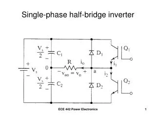
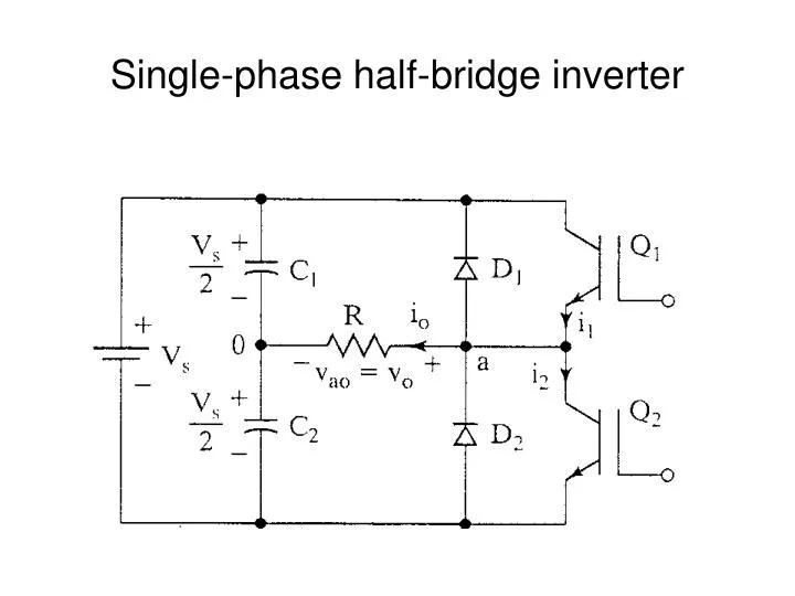
Single-phase half-bridge inverter. Operational Details. 3-wire DC source. Consists of 2 choppers, 3-wire DC source Transistors switched on and off alternately Need to isolate the gate signal for Q 1 (upper device) Each provides opposite polarity of V s /2 across the load.

E N D
Operational Details 3-wire DC source • Consists of 2 choppers, 3-wire DC source • Transistors switched on and off alternately • Need to isolate the gate signal for Q1 (upper device) • Each provides opposite polarity of Vs/2 across the load
Q1 on, Q2 off, vo = Vs/2 Peak Reverse Voltage of Q2 = Vs
Look at the output voltage rms value of the output voltage, Vo
Turn off Q1 at t = To/2Current falls to 0 via D2, L, Vs/2 lower + Vs/2 - + Vs/2 -
Turn off Q2 at t = ToCurrent falls to 0 via D1, L, Vs/2 upper + Vs/2 - + Vs/2 -
Load Current for a highly inductive load Transistors are only switched on for a quarter-cycle, or 90
DC Supply Current • If the inverter is lossless, average power absorbed by the load equals the average power supplied by the dc source. • For an inductive load, the current is approximately sinusoidal and the fundamental component of the output voltage supplies the power to the load. Also, the dc supply voltage remains essentially at Vs.
Performance Parameters • Harmonic factor of the nth harmonic (HFn) for n>1 Von = rms value of the nth harmonic component V01 = rms value of the fundamental component
Performance Parameters (continued) • Total Harmonic Distortion (THD) • Measures the “closeness” in shape between a waveform and its fundamental component
Performance Parameters (continued) • Distortion Factor (DF) • Indicates the amount of HD that remains in a particular waveform after the harmonics have been subjected to second-order attenuation. for n>1
Performance Parameters (continued) • Lowest order harmonic (LOH) • The harmonic component whose frequency is closest to the fundamental, and its amplitude is greater than or equal to 3% of the amplitude of the fundamental component.
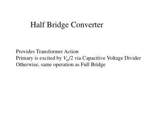
Operational Details • Consists of 4 choppers and a 3-wire DC source • Q1-Q2 and Q3-Q4 switched on and off alternately • Need to isolate the gate signal for Q1 and Q3 (upper) • Each pair provide opposite polarity of Vsacross the load
Q1-Q2 on, Q3-Q4 off, vo = Vs + Vs -