Download
1 / 80
800 likes | 1.28k Views
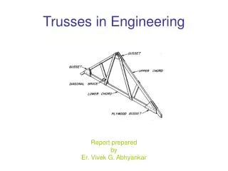
Trusses. Element Formulation by Virtual Work. Use virtual work to derive element stiffness matrix based on assumed displacements

E N D
Element Formulation by Virtual Work • Use virtual work to derive element stiffness matrix based on assumed displacements • Principle of virtual work states that if a general structure that is in equilibrium with its applied forces deforms due to a set of small compatible virtual displacements, the virtual work done is equal to its virtual strain energy of internal stresses.
At element level, dUe = dWe • dUe = virtual strain energy of internal stresses • dWe = virtual work of external forces acting through virtual displacements
We now assume a simple displacement function to define the displacement of every material point in the element. • Usually use low order polynomials • Here u = a1 + a2x • u is axial displacement • a1, a2 are constants to be determined • x is local coordinate along member
The constants are found by imposing the known nodal displacements ui, uj at nodes i and j ui = a1 + a2xi uj = a1 + a2xj • ui, uj are nodal displacements • xi, xj are nodal coordinates
letting xi= 0, xj = L, we get • a1= ui • a2 = (uj-ui)/L • We can write • [N] = matrix of element shape functions or interpolation functions • {d} = nodal displacements
N1=1 Variation of N1 N2=1 Variation of N2
Strain is given by • where [B] is a matrix relating strain to nodal displacement (matrix of derivatives of shape function)
Now s = E(e- eo )= E[B]{d}-E eo • Stress and strain are constant in a member • Define internal virtual strain energy for a set of virtual displacements {dd} to be
de = virtual strain • s = stress level at equilibrium • dV = volume • Virtual work of nodal forces is dWe = {dd}T{f} • Then, virtual work is given by
Substituting and rearranging gives • Canceling {dd}Tgives [k]{d}={F} where For thermal problem
for a truss we get • this formulation method also applies to 2-d and 3-d elements
Procedure for Direct Stiffness Method (Displacement Method) • Discretize into finite elements, Identify nodes, elements and number them in order. • Develop element stiffness matrices [Ke] for all the elements. • Assemble element stiffness matrices to get the global stiffness matrix ([KG] =S[Ke]). The size of of global stiffness matrix = total d.o.f of the structure including at boundary nodes. Assembly is done by matching element displacement with global displacements. Also develop appropriate force vector (by adding element force vectors) such that equation of the type [KG] {u}={F} is obtained.
Procedure for Direct Stiffness Method • Apply kinematic boundary conditions. Without applying boundary conditions, [KG] will be singular. (minimum number of boundary conditions required is to arrest ‘Rigid Body’ displacements). • Solve for unknown displacements {u} ( {u}= [KG] –1{F}). • Once displacements are determined find • (a) reactions by picking up appropriate rows from the equation {F}=[KG] {u}, (b) Find element forces {f}=[Ke] {ue}, (c) Element stresses given by {se}= [D][B]{ue}.
2A, L, E A, L, E
A, L, E 2A, L, E A, L, E Element Forces f2 f1
u2 u3 u1 u2
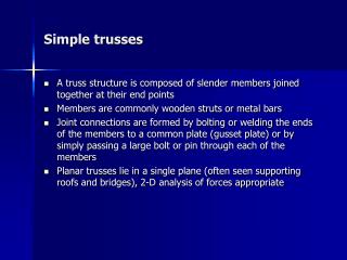
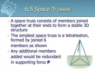
Direct Element Formulation • truss element acts like 1-d spring • l >> transverse dimensions • pinned connection to other members (only axial loading). • usually constant cross section and modulus of elasticity
A = cross section area • E = modulus of elasticity • L = length
Assume displacements are much smaller than overall geometry • vertical displacements of horizontal member produce no vertical force • Stiffness matrix is written in local element coordinates aligned along element axis • want stiffness matrix for arbitrary orientation
rotate coordinate systems using rotation matrix [R] • displacement components in global coordinates are related to displacement components in local coordinates by {d’}=[R]{d} • {d} = displacement in global coordinates • {d’} = displacement in local element coordinates
start with member on x axis, element equations are or {k’}{d’}={f’} • Note that y equations are all zero
At node i A similar matrix can be obtained at node j
Similarly , force components are related by {f’} = [R]{f} • Local force displacement relation is [k’]{d’} = {f’} • global force displacement relation is [k][R]{d} = [R]{f} • using fact that [R]-1 = [R]T, we get [R]T[k][R]{d} = {f}
then [k] = stiffness matrix in global coordinates is [R]T[k’][R]
Structure equation is [k] {D} = {F} • [k] = structure stiffness matrix • {D} = nodal displacement vector • {F} = applied load vector
2 C o o r d i n a t e C o o r d i n a t e E l e m e n t i - n o d e L e n g t h j - n o d e C s x y x y L 1 L c o s 4 5 L s i n 4 5 c o s 4 5 0 0 s i n 4 5 1 2 L 2 3 0 c o s 4 5 -s i n 4 5 2 L s i n 4 5 2 L c o s 4 5 L s i n 4 5