Download
1 / 11
110 likes | 224 Views
CLIC Transverse Profile Monitoring. CLIC Requirements. CTC. Critical issue identified for the CDR: ‘1um resolution Laser Wire Scanner’ Foreseen at the end of the Main Linac and in the BDS: Studied by RHUL Damping ring & RTML would need as well high precision measurements DR’s and TA’s

E N D
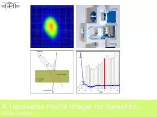
CLIC Transverse Profile Monitoring
CLIC Requirements CTC • Critical issue identified for the CDR: ‘1um resolution Laser Wire Scanner’ • Foreseen at the end of the Main Linac and in the BDS: Studied by RHUL • Damping ring & RTML would need as well high precision measurements • DR’s and TA’s • Based on Synchrotron Radiation (SR) techniques (X-ray, interferometry,..) • LWS could be used as well but more expensive • Transfer lines: • Thermal limitations of OTR screen in the range of ….. • Development of Degradable OTR screen • Need for non-interceptive beam diagnostic in the Drive Beam Complex • 20-50um resolution but with very high charge beams • Strategy here in the used classical interceptive devices (OTR) up to the thermal limit for screen • Option for Optical Diffraction Radiation, Synchrotron Radiation, LWS: • ODR could be used in straight section • Simple and cheap • Single shot measurements but no beam profile • Compatible 3-4 screens method instead of Quad scans • SR and LWS would need in bending magnet and be based on quad scans (need a DUMP afterwards)
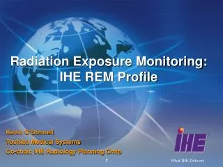
CLIC Transverse Beam size Requirements CTC Main Beam Drive Beam 102 10 DB Decelerator DB Injectorcomplex 1 MB Injectorcomplex 10-1 Beam size (mm) PDR & DR RTML Main Linac BDS 10-2 10-3 10-4 10-3 10-2 10-1 1 10 102 103 Beam energy (GeV)
CLIC Transverse Beam size Requirements CTC 102 DB Decelerator Zone Of Interest 10 DB Injectorcomplex 1 MB Injectorcomplex 10-1 Beam size (mm) PDR & DR n Linac & BDS 10-2 10-3 10-4 10-3 10-2 10-1 1 10 102 103 Beam energy (GeV)
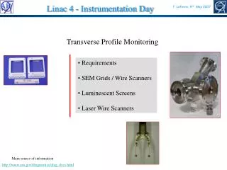
Available Techniques & limitations CTC ODR LWS SR Techniques OTR 102 DB Decelerator Optical Transition Radiation Limited by charge density Synchrotron Radiation Techniques Limit ? 10 DB Injectorcomplex 1 Optical Diffraction Radiation Limited by resolution ? MB Injectorcomplex 10-1 Beam size (mm) PDR & DR n Linac & BDS Laser Wire Scanner Ultimateresolution ? 10-2 10-3 10-4 10-3 10-2 10-1 1 10 102 103 Beam energy (GeV)
Potential Test Facilities CTC ODR LWS SR Techniques OTR 102 Optical Transition Radiation Synchrotron Radiation Techniques 10 1 Optical Diffraction Radiation 10-1 Beam size (mm) Laser Wire Scanner 10-2 10-3 10-4 10-3 10-2 10-1 1 10 102 103 Beam energy (GeV)
Thermal limitations of OTR screens CTC • Main Beam: 321 bunches with 3.72x10⁹ electrons • Assuming a reduced repetition rate ~1Hz during the measurement: For quad scans: beam should be dumped afterwards • Limited for thermal resistant screen (~3000oC): Max ~ 250um2 size density • - For a single bunch ~ 10um2: Would work but close to the limit (DR & RTML) • Drive Beam: 70128 bunches with 5x10¹⁰ electrons • For the full beam, it only works if the beam density >10cm2 : Never the Case ! • at the limit with a single Drive Beam: (0.36mm2) • Can be foreseen for the DB Decelerator because the beam envelope is becoming larger
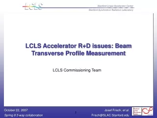
Spatial resolution limitation of ODR CTC • Principle of operation: Observe the interference pattern of diffraction radiation form two slits ‘Position of the peak ~ 1/g’ • Impact parameter to produce visible photons depending on the beam energy - For DB Energy: a~600um
Spatial resolution limitation of ODR CTC • Several machine have already observed ODR • Spatial resolution limitations still to be understood ! • Not an absolute measurement ! Method needs cross-calibration: Could be used to measure change in beam size - potentially a candidate for DB complex 7GeV Observed size: 200-1000um Signal distortion in near field: if the observer is at a distance L < lg2/2p 1.28GeV Low emittance Observed size: 10-70um
Next Step for R&D CTC • Laser Wire Scanner: • Demonstrate the resolution: Followed up by RHUL in test facilities: • ATF2 (1um resolution: Main Beam system) • PETRA (~ Drive Beam system) • CESR-TA ? • Integrate the monitor in the different areas of the CLIC complex: ‘Simulation‘ • Design of the detection system – including bends if necessary • First study in the CLIC main tunnel by Greg Penn in 2003 • Estimate the level of background – Acceptable beam loss level • Develop the technology: ‘Lab’ • High power Optical fiber laser for simplicity and cost optimization (Studied by Oxford / JAI) • Optical system and distributed systems for cost optimization • Develop detector for very high energy scheme • Synchrotron Radiation: to be followed through DR collaboration • Point spread function techniques: (done in PSI) • X-ray optics (done in several places: DESY / ALBA ?) • LWS (done in ATF2/KEK – CESRA-TA ?) • Optical Transition Radiation: • Demonstrate a resolution of 1um: RHUL colleagues in ATF2-KEK • Develop degradable monitor • Optical Diffraction Radiation: (ATF2 – CESR-TA) • Used for beam sizes in DB complex in Linear section: Cost saving compared to LWS • Used for non interceptive beam energy monitoring along the CLIC Main Beam linac
CLIC Transverse Beam size Requirements CTC 102 DB Decelerator 10 DB Injectorcomplex 1 MB Injectorcomplex 10-1 Beam size (mm) PDR & DR n Linac & BDS 10-2 10-3 10-4 10-3 10-2 10-1 1 10 102 103 Beam energy (GeV)