Download
1 / 30
300 likes | 317 Views
Explore the concept of beam phase rotation through simulations, focusing on an adiabatic buncher and Vernier rotation methods for high-frequency beam optimization at Fermilab. The study includes drift, decay, and cooling components, with the aim of achieving high performance while minimizing costs. Detailed simulations and matching procedures are outlined to demonstrate the effectiveness of the proposed beam optimization techniques.

E N D
Bunched-Beam Phase Rotation David Neuffer Fermilab
Outline • Introduction • “High-frequency” Buncher and Rotation • Concept • 1-D, 3-D simulations • Continuing Studies … • Variations • Matching, Optimization Study 3 • Match to Palmer cooling section • Obtains up to ~0.27 /p • Variations (shorter, …) cost performance optimum
Adiabatic buncher + Vernier Rotation • Drift (90m) • decay; beam develops correlation • Buncher(60m)(~333200MHz) • Forms beam into string of bunches • Rotation(~10m)(~200MHz) • Lines bunches into equal energies • Cooler(~100m long)(~200 MHz) • fixed frequency transverse cooling system Replaces Induction Linacs with medium-frequency rf (~200MHz) !
Longitudinal Motion (1-D simulations) Drift Bunch E rotate Cool System would capture both signs (+, -) !!
Adiabatic Buncher overview • Want rf phase to be zero for reference energies as beam travels down buncher • Spacing must be N rf rf increases (rf frequency decreases) • Match torf= ~1.5m at end: • Gradually increase rf gradient (linear or quadratic ramp): Example: rf : 0.901.5m
Adiabatic Buncher overview • Adiabatic buncher • Set T0, : • 125 MeV/c, 0.01 • In buncher: • Match torf=1.5m at end: • zero-phase with 1/ at integer intervals of : • Adiabatically increase rf gradient: rf : 0.901.5m
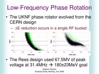
Rotation • At end of buncher, change rf to decelerate high-energy bunches, accelerate low energy bunches • With central reference particle at zero phase, set rf a bit less than bunch spacing (increase rf frequency) • Places low/high energy bunches at accelerating/decelerating phases • Can use fixed frequency (requires fast rotation) or • Change frequency along channel to maintain phasing “Vernier” rotation –A. Van Ginneken
“Vernier” Rotation • At end of buncher, choose: • Fixed-energy particle T0 • Second reference bunch TN • Vernier offset • Example: • T0 = 125 MeV • Choose N= 10, =0.1 • T10 starts at 77.28 MeV • Along rotator, keep reference particles at (N + ) rf spacing • 10 = 36° at =0.1 • Bunch centroids change: • Use Erf = 10MV/m; LRt=8.74m • High gradient not needed … • Bunches rotate to ~equal energies. rf : 1.4851.517m in rotation; rf = ct/10 at end (rf 1.532m) Nonlinearities cancel: T(1/) ; Sin()
First ICOOL Simulations • ICOOL Simulations • Include Transverse motion + realistic initial distributions • Initial beam – Study II target production • Transverse focusing - • 20 T(Target) 1.25T solenoid • 1.25 T focusing throughout (x = 10cm) • Buncher + E rotation • Use parameters approximating 1-D simulation; • Initial transport into Study 2 Cooling channel • Accepts only T =0.12 rms; ~40% loss by scraping • Up to ~0.2 obtained • Better with matched cooling ? T =0.20 rms;
Key Parameters • General • Muon capture momentum (200MeV/c?) 280MeV/c? • Baseline rf frequency (200MHz) • Drift • Length LD • Buncher– Length (LB) • Gradient, ramp VB (linear OK) • Final Rf frequency (LD + LB) (1/) = RF • Phase Rotator-Length (LR) • Vernier, offset : NR, V • Rf gradient VR • Match into cooling channel, Accelerator
Implementation in ICOOL • Define 2 reference particles: P1, P2 • ACCEL option 10 • N –wavelengths between ref particles • V(z) = A +Bz +Cz2 • Long. Mode • Phase model 0 or 1 • 0 at t1 (partREFP model 3 or 4icle 1) • 1 at (t1 + t2)/2 • 3 –constant velocity • 4 –energy loss + reference energy gain in cavities SREGION ! RF 0.50 1 1e-2 1 0. 0.30 ACCEL 10. 0. 0. 0. 5.05 1. 30. 15 0 0 0. 0. 0. 0. 0 VAC NONE 0. 0. 0. 0. 0. 0. 0. 0. 0. 0.
New Cooling Channel • Need initial cooling channel • (Cool T from 0.02m to 0.01m) • Longitudinal cooling ? • Examples • Solenoidal precooler (Palmer) • “Quad-channel” precooler • 3-D precooler • Match into precooler • First try was unmatched • Transverse match • B=Const. B sinusoidal • Gallardo, Fernow & Palmer
Palmer Dec. 2003 scenario • Drift –110.7m • Bunch -51m • (1/) =0.0079 • -E Rotate – 52m • P1=280 , P2=154V = 18.032 • Match and cool (100m) • P0 =214 MeV/c • 0.75 m cells, 0.02m LiH
Simulation results • (Palmer, Gallardo, Fernow,… • 0.25 /p in 30 mm acceptance
How many rf frequencies? • Example has new frequency every rf cavity • Elvira and Keuss explored how many different rf cavities were needed, using Geant4 • 60 initially • 20 OK • 10 also OK, but slightly worse performance • Need to go through this exercise for present scenario Only 20 frequencies and voltages. (20 equidistant linacs made of 3 cells)
Shorter bunch train (for Ring Cooler ?) • Ring Cooler requires shorter bunch train for single-turn injection – ~30m? • 200MHz example • –reduce drift to 20m (from 90) • -reduce buncher to 20m • Rotator is ~12m • ~85% within <~30m • Total rf voltage required is about the same (~200MV) • RFOFO cooler wants 12m bunch train !!! “Long” Bunch “Short” Bunch 2 scale
“Latest” short buncher • Drift – 20m • Bunch – 20m • Vrf = 0 to 15 MV/m ( 2/3) • P1 at 205.037, P2=130.94 • N = 5.0 • Rotate – 20m • N = 5.05 • Vrf = 15 MV/m ( 2/3) • Palmer Cooler up to 100m 40m 60m 95m
Simulation results • ICOOL results • 0.12 /p within 0.3 cm acceptance • Bunch train ~12 bunches long (16m) • (but not 8 bunches …)
FFAG-influenced variation – 100MHz • 100 MHz example • 90m drift; 60m buncher, 40m rf rotation • Capture centered at 250 MeV • Higher energy capture means shorter bunch train • Beam at 250MeV ± 200MeV accepted into 100 MHz buncher • Bunch widths < ±100 MeV • Uses ~ 400MV of rf
Hardware/Cost (Shelter Island Now) • Rf requirements: • Buncher: ~300~210 MHz; 0.14.8MV/m (60m) (~10 frequencies; ~10MHz intervals) • Rotator: ~210200 MHz; 10MV/m (~10m) • Transverse focussing • 160m B=1.25T solenoidal focusing;R=0.30m transport • 2002 cost estimate • (Rf =30M$ (Moretti); magnets =40M$(M. Green);conv. fac.,misc.20M$) ( ?? 100M$ ) • NOW – Rotator up to 50m, rf at least 40M$ (?) more • Transverse Focusing at 2T, R =0.25m, 200+ m long Need better/updated cost estimate; cost/performance optimization see Palmer’s talk
Summary • High-frequency Buncher and E Rotator simpler and cheaper (?) than induction linac system • Performance better (?) than study 2, And • System will capture both signs (+, -) ! (Twice as good ?) • Method could be baseline capture and phase-energy rotation for anyneutrino factory … To do: • Optimizations, Best Scenario, cost/performance …
~50 MHz variations Example I (250 MeV) • Uses ~90m drift + 100m 10050 MHz rf (<4MV/m) ~300MV total • Captures 250200 MeV ’s into 250 MeV bunches with ±80 MeV widths Example II (125 MeV) • Uses ~60m drift + 90m 10050 MHz rf (<3MV/m) ~180MV total • Captures 125100 MeV ’s into 125 MeV bunches with ±40 MeV widths
Variations/ Optimizations … • Many possible variations and optimizations • But possible variations will be reduced after design/construction • Shorter bunch trains ?? • For ring Coolers ? • Other frequencies ?? • 200 MHz(FNAL) 88 MHz ?? (CERN) ??? ~44MHz • Cost/performance optima for neutrino factory (Study 3?) • Collider ??both signs (+, -) ! • Graduate students (MSU) (Alexiy Poklonskiy, Pavel Snopok) will study these variations; optimizations; etc…
Hardware For Adiabatic Buncher • Transverse focussing (currently) • B=1.25T solenoidal focusing • R=0.30m transport for beam Rf requirements: • Buncher: ~300~210 MHz; 0.14.8MV/m (60m) (initially 1 cavity every 1m; reduces frequency in 2-4MHZ steps; 1-D and GEANT4 simulations indicate ~10 frequencies are sufficient (~10MHz intervals) • Rotator: 210200 MHz; 10MV/m (~10m)
Transport requirements • Baseline example has 1.25 T solenoid for entire transport (drift + buncher + rf rotation) (~170m) • Uncooled -beam requires 30cm radius transport (100m drift with 30cm IR – 1.25T) • In simulations, solenoid coils are wrapped outside rf cavities. (~70m 1.25T magnet with 65cm IR) • FODO (quad) transport could also be used …
Cost of magnets (M. Green) • 100m drift: 11.9 M$ (based on study 2) • Buncher and phase rotation: 26 M$ (study 2) • Cryosystem: 1.5M$; Power supplies 0.5M$ • Total Magnet System : 40M$ • (D. Summers says he can do Al solenoids for ~10 M$) • Would quad-focusing be cheaper ?
$$ Cost Savings ?? • High Frequency -E Rotation replaces Study 2: • Decay length (20m, 5M$) • Induction Linacs + minicool (350m, 320M$) • Buncher (50m, 70M$) • Replaces with: • Drift (100m) • Buncher (60m) • Rf Rotator (10m) • Rf cost =30M$; magnet cost =40M$ Conv. Fac. 10M$ Misc. 10M$ …… • Back of the envelope: (400M$ ?? 100M$ )