Download
1 / 37
370 likes | 498 Views
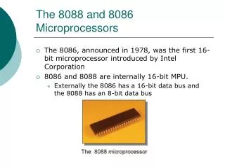
TK 2633 Microprocessor & Interfacing. Lecture 2: Introduction to 8085 Assembly Language Programming (2). Prepared By: Associate Prof. Dr Masri Ayob. Objectives. Explain the various functions of the registers in the 8085 programming model.

E N D
TK 2633Microprocessor & Interfacing Lecture 2: Introduction to 8085 Assembly Language Programming (2) Prepared By: Associate Prof. Dr MasriAyob
Objectives • Explain the various functions of the registers in the 8085 programming model. • Define the term flag and explain how the flags are affected. • Explain the terms operation code (Opcode) and the operand, and illustrate these terms by writing instructions. Prepared by: Dr Masri Ayob - TK2123
Objectives • Classify the instructions in terms of their word size and specify the number of memory registers required to store the instructions in memory. • List the five categories of the 8085 instruction set. • Define and explain the term addressing mode. Prepared by: Dr Masri Ayob - TK2123
Objectives • Write logical steps to solve a simple programming problem. • Draw a flowchart from the logical steps of a given programming problem. • Translate the flowchart into mnemonics and convert the mnemonics into Hex code for a given programming problem. Prepared by: Dr Masri Ayob - TK2123
The 8085 Hardware/Programming Model • A model is a conceptual representation of a real object. • The microprocessor can be represented in terms of its hardware (physical electronic components) and a programming model (information needed to write programs). Prepared by: Dr Masri Ayob - TK2123
8085 Hardware Model Prepared by: Dr Masri Ayob - TK2123
8085 Programming Model Prepared by: Dr Masri Ayob - TK2123
8085 Flag Register Prepared by: Dr Masri Ayob - TK2123
8085 Hardware Model • Two major segments: • One segment includes the arithmetic/logic unit (ALU) and an 8-bit register called an accumulator, instruction decoder, and flags. • The second segment shows 8-bit and 16-bit registers. • Both segments are connected with various internal connections called an internal bus. • The arithmetic and logical operations are performed in the ALU. Results are stored in the accumulator, and flip-flops, called flags, are set or reset to reflect the results Prepared by: Dr Masri Ayob - TK2123
8085 Hardware Model • There are three buses: • a 16-bit unidirectional address bus to send out memory addresses; • an 8-bit bidirectional data bus, and a control bus to transfer data, and. • the control bus for timing signals. Prepared by: Dr Masri Ayob - TK2123
8085 Programming Model • The model includes six 8-bit registers (B, C, D, E, H & L), one accumulator, and one flag register. • It also has two 16-bit registers: • the stack pointer (SP); • the program counter (PC). Prepared by: Dr Masri Ayob - TK2123
General-purpose Registers • The 8085 has six general-purpose registers to store 8-hit data; • B, C, D, E, H, and L. • They can be combined as register pairs - BC, DE, and HL - to perform some 16-bit operations. • The programmer can use these registers to store or copy data into the registers by using data copy instructions. Prepared by: Dr Masri Ayob - TK2123
Accumulator • The accumulator is an 8-bit register that is part of the arithmetic/logic unit (ALU). • This register is used to store 8-bit data and to perform arithmetic and logical operations. • The result of an operation is stored in the accumulator. • The accumulator is also identified as register A. Prepared by: Dr Masri Ayob - TK2123
Flags • The ALU includes five flip-flops, which are set or reset after an operation according to data conditions of the result in the accumulator and other registers. • They are called Zero (Z), Carry (CY), Sign (S), Parity (P), and Auxiliary Carry (AC) flags; Prepared by: Dr Masri Ayob - TK2123
Flags • The most commonly used flags are Zero, Carry, and Sign. The microprocessor uses these flags to test data conditions. • These flags have critical importance in the decision-making process of the microcessor. • E.g., the instruction JC (Jump On Carry) is implemented to change the sequence of a program when the CY flag is set. Prepared by: Dr Masri Ayob - TK2123
Flags • The following flags are set or reset after the execution of an arithmetic or logic operation; data copy instructions do not affect any flags. See the instruction set (Appendix F) to find how flags are affected by an instruction. • Z-Zero: The Zero flag is set to 1 when the result is zero; otherwise it is reset. • CY - Carry: If an arithmetic operation results in a carry, the CY flag is set; otherwise it is reset. Prepared by: Dr Masri Ayob - TK2123
Flags • S - Sign: The Sign flag is set if bit D7 of the result = 1; otherwise it is reset. • P - Parity: If the result has an even number of 1s, the flag is set; for an odd number of 1s, the flag is reset. • AC - Auxiliary Carry: In an arithmetic operation, when a carry is generated by digit D3 and passed to digit D4, the AC flag is set. This flag is used internally for BCD (binary-coded decimal) operations; there is no Jump instruction associated with this flag. Prepared by: Dr Masri Ayob - TK2123
Register contents before instruction Register contents after instruction: A 9A h A 23 h B 89 h B 89 h Flag 80 h Flag 10 h 1 0 0 1 1 0 1 0 1 0 0 0 1 0 0 1 Example ADD B Instruction: Note: All flags are modified to reflect the result of the addition. 0 0 1 0 0 0 1 1 Flag: S=0, Z=0, AC=1 , P=0 and C=1, Prepared by: Dr Masri Ayob - TK2123
Program COUNTER (PC) AND STACK POINTER (SP) • These are two 16-bit registers used to hold memory addresses. • PC: • The function of the PC is to point to the memory address from which the next byte is to be fetched. • When a byte (machine code) is being fetched, the program counter is incremented by one to point to the next memory location. Prepared by: Dr Masri Ayob - TK2123
Program COUNTER (PC) AND STACK POINTER (SP) • SP: • It points to a memory location in R/W memory, called the stack. • The beginning of the stack is defined by loading a 16-bit address in the stack pointer. • The PC will automatically update when calling to /returning from Subroutines. Prepared by: Dr Masri Ayob - TK2123
Stack • The stack is one of the most important things you must know when programming. • Think of the stack as a deck of cards. When you put a card on the deck, it will be the top card. Then you put another card, then another. • When you remove the cards, you remove them backwards, the last card first and so on. • The stack works the same way, you put (push) words (addresses or register pairs) on the stack and then remove (pop) them backwards. • That's called LIFO, Last In First Out. Prepared by: Dr Masri Ayob - TK2123
Stack • There are instructions that allow you to modify SP contents but you should NOT change the contents of that register if you don't know what you're doing! • PUSH • POP Prepared by: Dr Masri Ayob - TK2123
8085 Instruction Set • An instruction is a binary pattern designed inside a microprocessor to perform a specific function. • The entire group of instructions, called the instruction set, determines what functions the microprocessor can perform. Prepared by: Dr Masri Ayob - TK2123
8085 Instruction Set • Can be classified into the following five functional categories: • data transfer (copy) operations, • arithmetic operations, • logical operations, • branching operations, and • machine-control operations. Prepared by: Dr Masri Ayob - TK2123
Data Transfer (copy) Instructions • Copies data from a location called a source to another location, called a destination, without modifying the contents of the source. • In technical manuals, the term data transfer is used for this copying function. • The term transfer is misleading; it creates the impression that the contents of a source are destroyed when, in fact, the contents are retained without any modification. Prepared by: Dr Masri Ayob - TK2123
Data Transfer (copy) Instructions Prepared by: Dr Masri Ayob - TK2123
Arithmetic Operations • These instructions perform arithmetic operations such as addition, subtraction, increment, and decrement. • Addition - Any 8-bit number, or the contents of a register, or the contents of a memory location can be added to the contents of the accumulator and the sum is stored in the accumulator. • No two other 8-bit registers can be added directly (e.g., the contents of register B cannot be added directly to the contents of register C). The instruction DAD is an exception; it adds 16-bit data directly in register pairs. Prepared by: Dr Masri Ayob - TK2123
Arithmetic Operations • Subtraction - Any 8-bit number, or the contents of a register, or the contents of a memory location can be subtracted from the contents of the accumulator and the results stored in the accumulator. • The subtraction is performed in 2’s complement, and the results, if negative, are expressed in 2’s complement. No two other registers can be subtracted directly. Prepared by: Dr Masri Ayob - TK2123
Arithmetic Operations • Lncrement/Decrement - The 8-bit contents of a register or a memory location can be incremented or decremented by 1. • Similarly, the 16-bit contents of a register pair (such as BC) can be incremented or decremented by I. These increment and decrement operations differ from addition and subtraction in an important way; i.e., they can be performed in any one of the registers or in a memory location. Prepared by: Dr Masri Ayob - TK2123
Logical Operations • These instructions perform various logical operations with the contents of the accumulator. • AND, OR, Exclusive-OR - Any 8-bit number, or the contents of a register, or of a memory location can be logically ANDed, ORed, or EXORed with the contents of the accumulator. • The results are stored in the accumulator. • Rotate - Each bit in the accumulator can be shifted either left or right to the next position. Prepared by: Dr Masri Ayob - TK2123
Logical Operations • Compare - Any 8-bit number, or the contents of a register, or a memory location can be compared for equality, greater than, or less than, with the contents of the accumulator. • Complement - The contents of the accumulator can be complemented; all 0s are replaced by 1s and all 1s are replaced by 0s. Prepared by: Dr Masri Ayob - TK2123
Branching Operations • This group of instructions alters the sequence of program execution either conditionally or unconditionally: • Jump - Conditional jumps are an important aspect of the decision-making process in programming. These instructions test for a certain condition (e.g., Zero or Carry flag) and alter the program sequence when the condition is met. • This set includes an instruction called unconditional jump. Prepared by: Dr Masri Ayob - TK2123
Branching Operations • Call, Return, and Restart -These instructions change the sequence of a program either by calling a subroutine or returning from a subroutine. • The conditional Call and Return instructions also can test condition flags. Prepared by: Dr Masri Ayob - TK2123
Machine Control Operations • These instructions control machine functions such as Halt, Interrupt, or do nothing. Prepared by: Dr Masri Ayob - TK2123
Review of the 8085 Operations • In data transfer, the contents of the source are not destroyed; only the contents of the destination are changed. • The data copy instructions do not affect the flags. • Arithmetic and logical operations are performed with the contents of the accumulator, and the results are stored in the accumulator (with some exceptions). • The flags are affected according to the results. Prepared by: Dr Masri Ayob - TK2123
Review of the 8085 Operations • Any register including memory can be used for increment and decrement. • A program sequence can be changed either conditionally or by testing for a given data condition. Prepared by: Dr Masri Ayob - TK2123