Download
1 / 6
60 likes | 83 Views
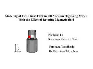
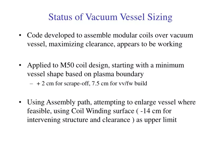
A code is developed for modular coil assembly over a vacuum vessel to maximize clearance, starting with the plasma boundary shape + 9.5 cm. Utilizing the Assembly Path to enlarge the vessel where feasible with a focus on Coil Winding surface.

E N D
Status of Vacuum Vessel Sizing • Code developed to assemble modular coils over vacuum vessel, maximizing clearance, appears to be working • Applied to M50 coil design, starting with a minimum vessel shape based on plasma boundary • + 2 cm for scrape-off, 7.5 cm for vv/fw build • Using Assembly path, attempting to enlarge vessel where feasible, using Coil Winding surface ( -14 cm for intervening structure and clearance ) as upper limit
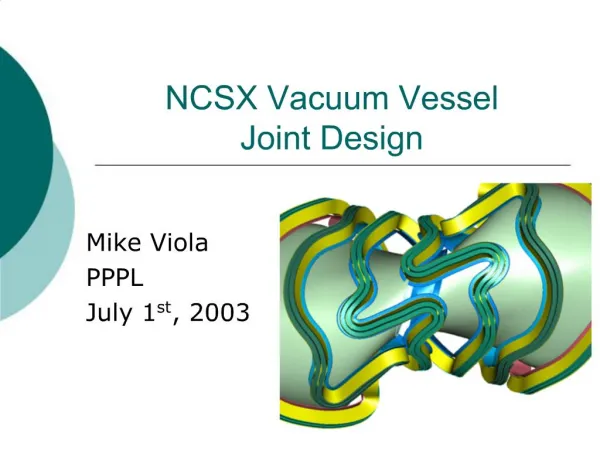
Envelope for Defining Vacuum Vessel Minimum Vessel ( plasma + 9.5 cm ) Maximum Vessel ( winding surface – 14 cm )
Assembly of M50 over Plasma + 9.5cm Clearance during assembly no worse than final assembly Rotation Clearance Displacement Assembled Disassembled
Sizing of Vessel still work in progress Minimum Vessel ( plasma + 9.5 cm ) Maximum Vessel traced out by assembly path Maximum Vessel ( winding surface – 14 cm )