Download
1 / 36
370 likes | 531 Views
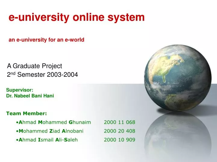
e-university online system an e-university for an e-world. A Graduate Project 2 nd Semester 2003-2004. Supervisor: Dr. Nabeel Bani Hani Team Member: A hmad M ohammed G hunaim 2000 11 068 M ohammed Z iad A lnobani 2000 20 408 A hmad I smail A li- S aleh 2000 10 909. Contents.

E N D
e-university online systeman e-university for an e-world A Graduate Project 2nd Semester 2003-2004 • Supervisor: • Dr. Nabeel Bani Hani • Team Member: • Ahmad Mohammed Ghunaim 2000 11 068 • Mohammed Ziad Alnobani 2000 20 408 • Ahmad Ismail Ali-Saleh 2000 10 909
Contents • Objectives • Introduction • Theoretical Background - (Vision) • System Requirement • System Analysis • System Design • System Implementation and Testing • Result Discussion - (Conclusion & Future Work) • Glossary • References
Objectives • After completing this presentation, you should be able to: • Understand e-university online systems capabilities. • Get closer to the steps we followed in developing this system.
Introductionincluding Contribution & Literature Review • The emerging of e-technology is having a major impact across many sectors of the economy. • That enforces us to respond quickly and imaginatively to these e-technologies, where a traditional ways of doing things will evaporate. • E-University Online System can provide many services, not only the same frames that know by people but also more useful features that provided by this new System capability, that satisfies large number of users and their needs.
Introduction [cont.] The aims of the e-university are - To improve, diversify and extend university's services - To be more effective and efficient - To be more attraction and competitive in a local and global marketplace
Theoretical Background - (Vision) • The purpose is to collect analyze and define high level needs features of the e-university online system. • Business Opportunity: This project will be replacing the existing traditional learning in universities with an e-university on-line system that allows admin, manager, tutor and student access via Internet capability.
Theoretical Background - (Vision) [cont.] • Stakeholder and user description
Theoretical Background - (Vision) [cont.] • Product Overview Illustrate the Project Architecture
Theoretical Background - (Vision) [cont.] External system used in e-university online system
System Requirement • Requirement model • Requirements capture: From Vision to Requirements
System Requirement [cont.] • Capturing Requirements as Use Cases • Problem statement • Use case diagram – see the next slide • Use case specification • Supplementary specification
System Requirement [cont.] • Activity diagram
System Analysis • Analysis Model • Analysis Class • Use Case Realization-Analysis • Class Diagram • Collaboration Diagram • Analysis Packages
System Analysis[cont.] • Analysis Model • Analysis Class • Use Case Realization-Analysis • Class Diagram • Collaboration Diagram • Analysis Packages All Boundary classes are an ASP. net pages (an attribute – Languages used). All Control classes are Programmed as classes in Asp.net Language (Classes here is an Object Oriented Concept) All the entity classes are tables in the project Database. (For more details about Tables please refer to the Design Section)
System Analysis[cont.] • Analysis Model • Analysis Class • Use Case Realization-Analysis • Class Diagram • Collaboration Diagram • Analysis Packages The Analysis Classes that participate in a realization of the affiliate to the system. The visitor panel is a boundary, the affiliate is a control class, and the visitor profile is an entity class The Analysis Classes that participate in a realization of the ask for help. The student panel is a boundary, the ask for help is a control class, and the help is/are an entity class The realization of a use case in the Analysis Model Sample: 2of 20
System Analysis[cont.] • Analysis Model • Analysis Class • Use Case Realization-Analysis • Class Diagram • Collaboration Diagram • Analysis Packages A class diagram for realization of the affiliate to the system use case A class diagram for realization of the ask for help use case The Class Diagram in the Analysis Model –Sample: 2of 20
System Analysis[cont.] • Analysis Model • Analysis Class • Use Case Realization-Analysis • Class Diagram • Collaboration Diagram • Analysis Packages A collaboration diagram for a realization of the affiliate to the system use case. A collaboration diagram for a realization of the ask for help use case The Collaboration Diagram in the Analysis Model –Sample: 2of 20
System Analysis[cont.] • Analysis Model • Analysis Class • Use Case Realization-Analysis • Class Diagram • Collaboration Diagram • Analysis Packages
System Design • Design Model • Design Classes • Use Case Realization- Design • Sequence Diagram • Data Base Design The design model is an object model describing the realization of use cases, and serves as an abstraction of the implementation model and its source code. The design model is used as essential input to activities in implementation and test.
System Design [cont.] • Design Model • Design Classes • Use Case Realization- Design • Sequence Diagram • Data Base Design The design model is more "physical" in nature, whereas the analysis model is more "conceptual". This class is for facilitate the affiliate process, where used in the visitor affiliate form. This class is for login operation, which makes all things needed to reserve the security issues. The Class Diagram in the Design Model –Sample: 2of 14
System Design [cont.] • Design Model • Design Classes • Use Case Realization- Design • Sequence Diagram • Data Base Design e-admin subsystem The Use Case Realization- Design in the Design Model –Sample: 2of 8 subsystem
System Design [cont.] • Design Model • Design Classes • Use Case Realization- Design [cont.] • Sequence Diagram • Data Base Design The classes participating in the realization of the affiliate to the system use case and their association Class Diagrams – within a use case realization-design Here, we collect the design classes participating in use-case realization in a class diagram associated with the realization. Class diagrams are used to show the relationships that are employed in the use-case realization. The Class Diagram in the Design Model –Sample: 1of 20
System Design [cont.] • Design Model • Design Classes • Use Case Realization- Design • Sequence Diagram • Data Base Design A sequence diagram that is part of a realization of the affiliate to the system use case in the design model A sequence diagram describes a pattern of interaction among objects, arranged in a chronological order; it shows the objects participating in the interaction by their "lifelines" and the messages that they send to each other. The Sequence Diagram in the Design Model –Sample: 1of 20
System Design [cont.] • Design Model • Design Classes • Use Case Realization- Design • Sequence Diagram • Data Base Design
Design Model Design Classes Use Case Realization- Design Sequence Diagram Data Base Design [cont.] System Design [cont.] Tables Notations
Implementation Model Database Implementation Main Screen Shots Test Model System Implementation and Testing The SQL scripts that used in the e-university online system are mention below with their related view the table design. tables are programmed using the MS SQL server 2000). CREATE TABLE [dbo].[UserAccounts] ( [UserID] [nvarchar] (50) COLLATE Arabic_CI_AS NOT NULL , [FirstName] [nvarchar] (50) COLLATE Arabic_CI_AS NULL , [MiddleName] [nvarchar] (50) COLLATE Arabic_CI_AS NULL , [LastName] [nvarchar] (50) COLLATE Arabic_CI_AS NULL , [Gender] [nvarchar] (50) COLLATE Arabic_CI_AS NULL , [Status] [nvarchar] (50) COLLATE Arabic_CI_AS NULL , [POBox] [nvarchar] (50) COLLATE Arabic_CI_AS NULL , [Country] [nvarchar] (50) COLLATE Arabic_CI_AS NULL , [City] [nvarchar] (50) COLLATE Arabic_CI_AS NULL , [Email] [text] COLLATE Arabic_CI_AS NULL , [Phone] [bigint] NULL , [BirthDate] [datetime] NULL , [Role] [nvarchar] (50) COLLATE Arabic_CI_AS NULL , [AffiliateDate] [datetime] NULL , [Note] [nvarchar] (50) COLLATE Arabic_CI_AS NULL ) ON [PRIMARY] TEXTIMAGE_ON [PRIMARY] GO Database in Implementation Model –Sample: 1of 12
ImplementationModel Database Implementation Main Screen Shots Test Model System Implementation and Testing [cont.]
Implementation Model Database Implementation Main Screen Shots Test Model System Implementation and Testing [cont.] This project has been verified and validated to all measurement testing successfully
Result Discussion - (Conclusion & Future Work) E-university online system is a huge system and it is divided into subsystems. This project covered the main assets in the whole subsystem and each subsystems it has extend and dynamic characteristics to the future requirement changing. • The e-university online system now has: • e-management • e-faculty • e-office • e-user • e-academic • e-tutor • e-learning • e-courseware • e-student • e-services • e-affiliation • e-information • e-guidance • Chat • Forum • The intent Future work is around the completion of: • e-graduating subsystem • e-library subsystem • e-training subsystem • e-calendar subsystem • e-mail subsystem • e-payment subsystem (The Billing System) The main of our objective that is the real execution of this system in a real world, may in future we set up the e-university online system to achieve and reach our slogan of the system 'an e-university for an e-world'
Glossary • EUOS : E-University Online System • V.S.NET : Visual Studio .Net • RUP : Rational Unified Process • ASP : Active Server Pages • DB : Database
References • [REF: 1] I.Jacobson, G.Booch, J.Rumbaugh, Rational Software corporation "The Unified Software development Process", AddisonWesley 1999. • [REF: 2] Elmasri, Navathe, "Fundamentals of Database Systems", 3rd Edition 2000, • [REF: 3] Ian Sommerville, "Software Engineering", AddisonWesley • 6th Edition 2001. • [REF: 4] MSDN Library for Visual Studio .NET 2003, a soft copy. • [REF: 5] Rational Unified Process, Soft Copy , installed with Rational Suite Enterprise 2000. Electronic References • [REF: 6] http://www.dlcoursefinder.com • [REF: 7] http://www.asp.net
Special Thanks to:Chairman & Member of Approval CommitteeSpirit of the team unity Supervisor Dr. Nabeel M. Bani Hani Philadelphia University – Jordan e-university online systeman e-university for an e-world http://E-University.cjb.net